Wide-band ratiometric radio frequency bridge

Inactive Publication Date: 2002-11-26
HOLT KENNETH DAVID
View PDF5 Cites 31 Cited by
  • Summary
  • Abstract
  • Description
  • Claims
  • Application Information

AI Technical Summary

Benefits of technology

The described invention provides a low cost approach to improve, over prior art, measuring accuracy, bandwidth, range of measurable impedance values and ambient temperature operating range when measuring unknown complex impedance values. The bridge design provides for one side of the unknown impedance, Z.sub.X, to be grounded, which is desirable in most high frequency measurements, and minimizes any undesirable loading effects a

Problems solved by technology

Measuring accuracy and bandwidth for the circuit of FIG. 1 are primarily limited by measuring devices M.sub.1 through M.sub.4, the accuracy and purity of the resistive bridge elements and stray inductances, capacitances and resistances associated with the physical embodiment of FIG. 1.
When detecting small voltage levels, the non-linear diode characteristics cause dead zones where no useful voltage is detected thus causing measurement drop-outs.
Variations of the diode junction voltages, induced by ambient temperature fluctuations, will further add to inaccuracies in detected voltages.
Forward d.c. biasing of the diodes as well as compensation for the above cited errors, in the computing device for determining .vertline.Z.sub.X.vertline., .vertline..rho..vertline., VSWR, R.sub.X or unsigned X.sub.X, provides some improvement but accuracy is still severely limite

Method used


Image

  • Wide-band ratiometric radio frequency bridge
  • Wide-band ratiometric radio frequency bridge
  • Wide-band ratiometric radio frequency bridge

Examples


Example

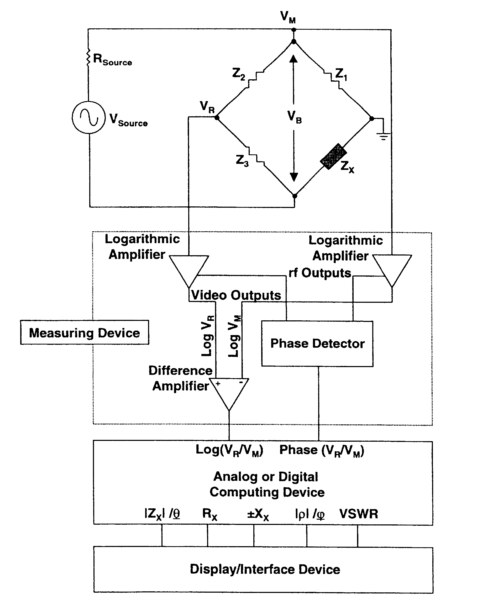
The invention, illustrated in FIG. 3, comprises an asymmetrical rf bridge, a measuring device, a computing device and a display or interface device. The bridge comprises three sides with known general impedance values (Z.sub.1, Z.sub.2 and Z.sub.3) and a forth side containing an unknown impedance value, Z.sub.X, to be measured. Z.sub.X is connected to the rf bridge circuit with a commercially available wide band rf connector of which one side is grounded, a desirable feature of this invention. In one embodiment of the invention Z.sub.1 through Z.sub.2 are implemented as resistors shunted by compensation capacitors. All components are selected to maintain their accuracy over a wide frequency band and wide ambient temperature range. A wide band rf source connects across the bridge vertical diagonal.

The measuring device comprises two wide band logarithmic amplifiers, a difference amplifier and a phase detector. A first logarithmic amplifier input is connected to the bridge at a left si...


PUM


Abstract

A radio frequency bridge, useful for measuring complex values of an unknown impedance or associated complex reflection coefficient and VSWR value, which comprises an rf source, a novel asymmetrical bridge, a measuring device (comprising two logarithmic amplifiers, a difference amplifier and a phase detector), a computing device and a display or interface device. The complex impedance may be any two terminals of a general N-port network not to exclude an antenna with or without feed-line. The invention is more accurate than prior art when measuring complex impedance values having magnitudes from approximately five ohms to an upper value limited only by the dynamic range of the logarithmic amplifiers, normally greater than 4000 ohms. It has the great advantage of maintaining constant measuring accuracy over a wide measuring range and can be designed to operate over very wide bandwidths.

Description

BACKGROUND OF INVENTION1. Field of InventionThis invention relates to electronic bridge networks as used for the measuring of complex electrical impedance values comprising resistive (real) and reactive (imaginary) components.2. Description of Prior ArtFIG. 1 illustrates a bridge configuration that is most commonly used in low cost radio frequency (rf) bridge based measuring instruments. Instruments of this type determine the complex electrical impedance magnitude (.vertline.Z.sub.X.vertline.) and the associated reflection coefficient magnitude (.vertline..rho..vertline.) for the complex impedance value being measured. Magnitude values for the real (R.sub.X) and unsigned reactive (X.sub.X) components as well as Voltage Standing Wave Ratio (VSWR), as taught by Paul's seminal U.S. Pat. No. 2,323,076 (1940), are then derived.Referring to FIG. 1, V.sub.source is an alternating current (a.c.) voltage source at a frequency of interest for the measurement. Z.sub.X is a complex impedance wh...

Claims


Application Information

Patent Timeline
IPC IPC(8): G01R17/10G01R17/00
CPCG01R17/105
Inventor HOLT, KENNETH DAVID
Owner HOLT KENNETH DAVID
Why Eureka
Try Eureka