Tool changer for machine tool

a tool changer and machine tool technology, applied in the field of tool changers, can solve the problems of consuming a great amount of electric power and a large weight, and achieve the effects of reducing the weight of the tool changer and the machine tool, improving the structure, and facilitating rotation or driving

Inactive Publication Date: 2009-09-29
XIAO ALAN
View PDF14 Cites 7 Cited by
  • Summary
  • Abstract
  • Description
  • Claims
  • Application Information

AI Technical Summary

Benefits of technology

[0009]The primary objective of the present invention is to provide a tool changer including an improved structure for decreasing the weight of the tool changer and the ma

Problems solved by technology

However, the disc magazine is made of an integral cast material and includes a great weight that may not be easily operated or rotated or driven by the motor driv

Method used


Image

  • Tool changer for machine tool
  • Tool changer for machine tool
  • Tool changer for machine tool

Examples


Embodiment Construction

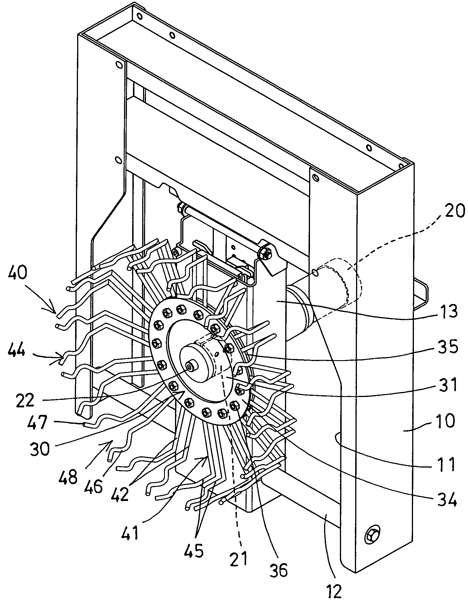
[0027]Referring to the drawings, and initially to FIG. 1, a tool changer in accordance with the present invention comprises a supporting base or frame or housing 10 for attaching to a machine tool (not shown), and including a chamber 11 formed in the housing 10, and including one or more tracks or rails 12 attached or disposed in the chamber 11 of the housing 10 for slidably attaching or supporting a follower or sliding member or carrier 13. A motor or motor driving device 20 is attached to the carrier 13 includes a spindle 21 extended in or out of the carrier 13 for attaching or supporting a disc magazine 30.

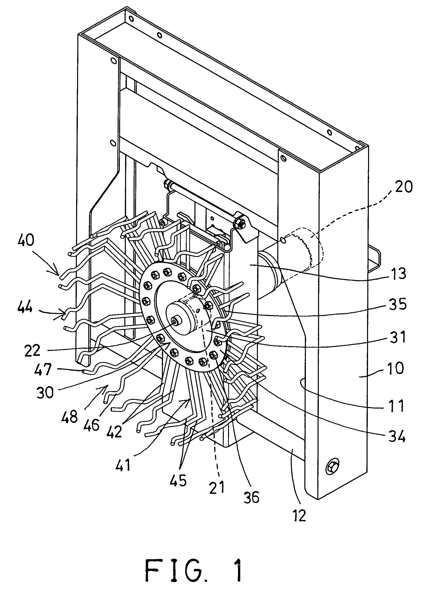
[0028]As shown in FIGS. 2-5, the disc magazine 30 of the tool changer includes a base or central plate 31 having a number of openings 32 formed in the outer peripheral portion 39 thereof and preferably equally spaced from each other, and opened radially and outwardly therefrom for attaching or receiving retainers 40 therein, and the retainers 40 are provided for detachably rece...


PUM


Abstract

A tool changer for a machine tool includes a disc magazine having a plate, and a number of retainers attached to the outer peripheral portion of the plate for detachably supporting tool members, the retainers each include a base portion attached to the outer peripheral portion of the plate, and a holding device disposed on the base portion and having two arms for resiliently holding and carrying and supporting the tool member. The retainers each include a coupling portion coupled between two legs, the arms of the holding devices may be extended from the legs and may be formed from a longitudinal wire or rod member for reducing the weight of the retainers.

Description

BACKGROUND OF THE INVENTION[0001]1. Field of the Invention[0002]The present invention relates to a tool changer, and more particularly to a tool changer for a machine tool including an improved structure for decreasing the weight of the tool changer and the machine tool and for allowing the tool changer to be easily rotated or driven by the motor driving device, and also for reducing the manufacturing cost for the machine tool, and also for allowing the tool changer to be easily and quickly formed and manufactured and to be easily and quickly assembled together.[0003]2. Description of the Prior Art[0004]Typical machine tools, particularly the programmable machine tools comprise a tool member rotated or driven by a motor driving device for machining various work pieces, and one or more disc magazines rotatably secured or disposed on a supporting base and having a number of notches formed in the peripheral portions of the disc magazines for supporting a number of spare tool members. T...

Claims


Application Information

Patent Timeline
IPC IPC(8): B23Q3/157
CPCB23Q3/15553B23Q3/15733B23Q3/1576Y10T483/1809Y10T483/1882
Inventor XIAO, ALAN
Owner XIAO ALAN
Why Eureka
Try Eureka