Shoe housing

a technology for shoes and housings, applied in the field of shoes, can solve the problems of affecting the movement of wearers, affecting the wearer's movement,

Active Publication Date: 2009-10-06
ADIDAS
View PDF185 Cites 106 Cited by
  • Summary
  • Abstract
  • Description
  • Claims
  • Application Information

AI Technical Summary

Benefits of technology

[0010]The present invention is based on the realization that the required circuits for electronic assemblies have become smaller and can, therefore, be easily arranged in a recess of the sole of a shoe without significantly affecting the functional properties of the sole (e.g., cushioning and support). At the same time, the electronic assembly is completely enclosed and, therefore, perfectly protected against mechanical impacts. An arrangement in a recess of the sole is also aesthetically pleasing, since the housing of the electronic assembly can not be recognized from the outside.
[0012]The detachable arrangement of the housing also makes the replacement of one electronic assembly for another electronic assembly having a different functionality easy. A unit for detection of a running movement by counting steps or measuring accelerations can thus be exchanged directly against another assembly, for example, a GPS receiver for position determination, a pulse sensor, or other electronic function units. The exchangeability is particularly desirable in the context of an intelligent shoe, where the cushioning properties of the sole can be changed under the control of an electronic control unit. If this control unit is defective, needs to be provided with new firmware, or needs to be exchanged for a more recent model, a mounting arrangement in accordance with the invention can be used in a particularly effective manner. It is also possible for the assembly to be removed in order to exchange, read, expand, etc., the memory of the electronic assembly.
[0015]The sole unit can include an opening or window adapted to permit a wearer to inspect and / or operate the electronic assembly. An additional user interface can also be provided on the shoe. In one embodiment, the recess and housing can be arranged in a midsole of the sole unit, where the sole unit also includes a removable insole for covering the recess when the article is in use. If the housing is arranged in such a recess, it is well protected, since it is surrounded by sole material from all sides. The insole is typically removable and, therefore, does not impair the direct access to the housing of the electronic assembly for, for example, changing the battery. In addition, a shape of the recess can correspond to a shape of the housing for the electronic assembly. The complementary shapes can aide in the retention of the housing within the sole unit by providing a positive fit when the housing is inserted, so that the housing is arranged substantially without play inside the recess of the sole. Vibrations, which after some time could damage an electronic assembly arranged inside the housing, are, therefore, essentially eliminated.
[0020]In additional embodiments, the housing includes a cover made of an elastic material. In one embodiment, the cover may encompass substantially the entire housing. Thus, a firm fit in the shoe's recess is on the one hand obtained and, on the other hand, the housing is protected if it is removed from the recess and, for example, falls onto a hard floor. The housing can include a seal arranged between the first portion and the second portion. In one embodiment, the housing includes an opening defined at least partially by at least one of the first portion and the second portion. The opening can be configured to enable access to an interior portion of the housing by a user. The housing can also include a mounting cover engageable with an attachment means for securing the article of footwear to a wearer's foot, the mounting cover configured to releasably receive and at least partially circumscribe the housing. The housing may also be releasably attached in a conventional manner to any arbitrary shoe, if the shoe does not provide a suitable recess in the shoe sole. The use of the housing and the electronic assembly arranged therein does, therefore, not necessarily require the use of a unique pair of shoes. Moreover, the mounting cover makes it possible to use the assembly additionally or alternatively for a display or the like, being arranged on the laces and displaying data measured and / or generated by a further assembly within the shoe.

Problems solved by technology

Whereas it is comparatively easy to mount a computer to a bicycle, there exists a problem in the case of running.
A similar problem occurs if a runner intends to carry other types of computers, such as, for example, a MP3 player.
Although it is generally possible to attach such an electronic assembly to the body using a strap or the like, such an attachment can be uncomfortable and impede movement of the wearer during a high performance activity.
All of these arrangements of a computer on a shoe have, however, the disadvantage that the sensitive electronic components of the computer are protected insufficiently against damage.
When the runner stumbles or falls, there is a significant risk that the housing of the computer, which is typically made from plastic materials, is subjected to mechanical loads that it can not withstand.
Protective coatings, which can be effective, are excluded, since the electronic assembly would reach a size and weight impairing performance of the wearer when the electronic assembly is arranged on the outside of the shoe.

Method used


Image

  • Shoe housing
  • Shoe housing
  • Shoe housing

Examples


Embodiment Construction

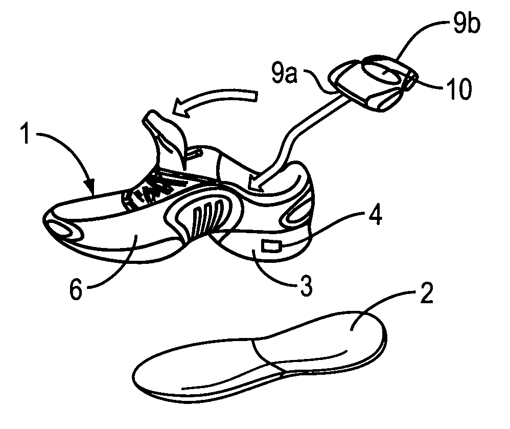
[0038]In the following, embodiments of the invention are described with reference to an electronic pedometer in a running shoe. The following interprets the term “pedometer” as any electronic assembly detecting in any manner the running movement electronically, e.g., to determine the number of steps done, the acceleration, the speed, or other physical values in connection with the running movement. It is, however, to be understood that the present invention also relates to the arrangement of other kinds of small electronic assemblies in shoes, including, but not limited to a shock sensor, a global positioning system, a pulse sensor, an accelerometer, a speed sensor, and an MP3 player.

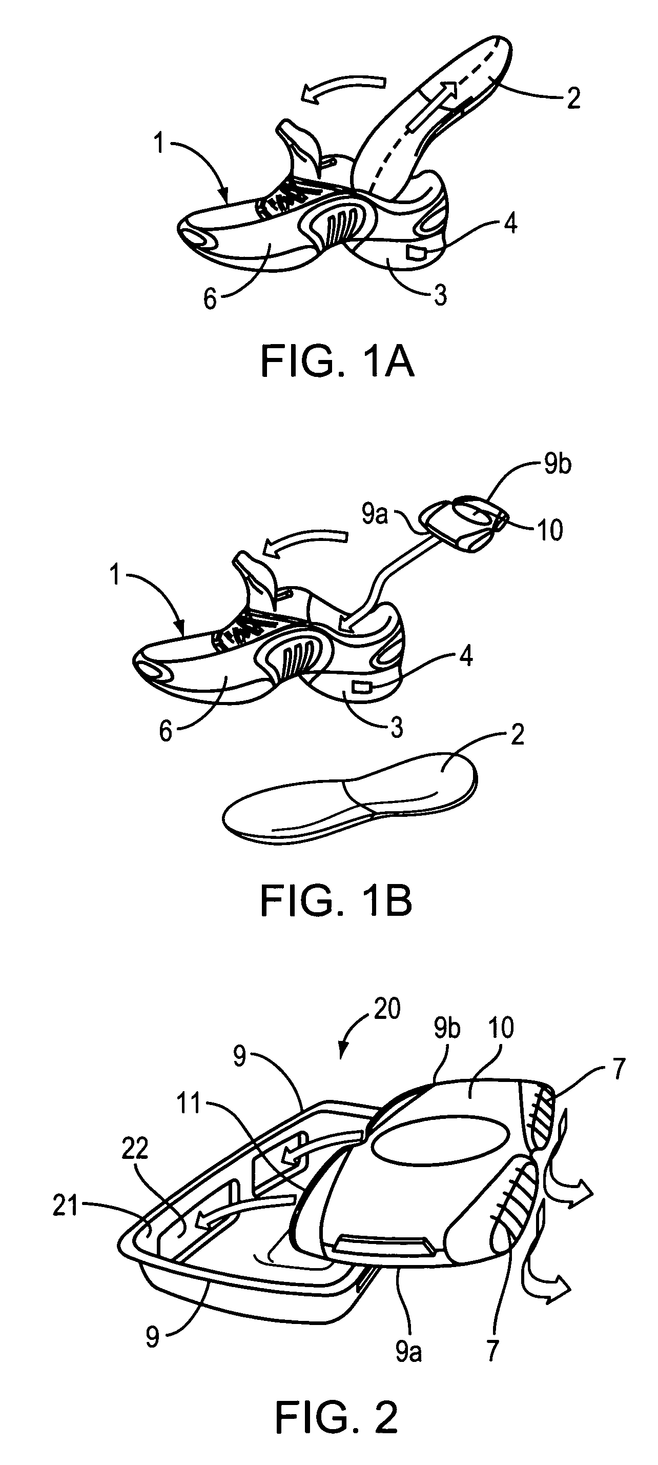
[0039]FIGS. 1A and 1B depict an electronic device, such as a pedometer, provided inside a housing 10 having a front end 9a and a rear end 9b arranged in a recess of a sole 3 of a shoe 1 including an upper 6. To this end, a removable insole 2 or a so-called sock liner is at first removed from within the ...


PUM


Abstract

The invention relates to a shoe with a sole unit, where the sole unit includes a recess for removably receiving a housing of an electronic assembly, for example, an electronic pedometer, an accelerometer, or a speed sensor. Further, the invention relates to a housing for receiving an electronic assembly, for example, a pedometer, an accelerometer, or a speed sensor, where the housing has an outer shape corresponding to the shape of a recess formed in a shoe sole.

Description

CROSS-REFERENCE TO RELATED APPLICATION[0001]This application incorporates by reference, and claims priority to and the benefit of, German patent application Ser. No. 102005014709.7, which was filed on Mar. 31, 2005, the entire disclosure of which is hereby incorporated herein by reference.TECHNICAL FIELD[0002]The present invention relates to a shoe for receiving a housing of an electronic assembly and to a housing for receiving an electronic assembly.BACKGROUND[0003]Professional athletes, as well as amateurs, desire in an increasing number of sports to electronically keep track of their athletic performance. For example, electronic speedometers with a plurality of functions are nowadays standard equipment for every ambitious race or mountain biker. Small computers are also used for running to count the number of steps, the speed, and thus the covered distance, and can provide additional information.[0004]Whereas it is comparatively easy to mount a computer to a bicycle, there exists...

Claims


Application Information

Patent Timeline
Patent Type & Authority Patents(United States)
IPC IPC(8): A43B5/00A43B13/18A43B3/35
CPCA43B3/00A43B3/0005A43B3/0031G01C22/006A61B5/11A61B5/1036A43B3/34
Inventor CARNES, JAMESTOMLINSON, SCOTTVINCENT, STEPHEN MICHAEL
Owner ADIDAS
Why Eureka
Try Eureka