Conveyor screw for use as surface scraper in cooling and freezing units

a technology of conveyor screw and surface scraper, which is applied in the direction of rotary stirring mixer, mixing, chemistry apparatus and processes, etc., can solve the problems of high power consumption for cooling, inefficient freezer, and generation of heat in the ice cream mass, so as to reduce the power of conveyancing and convey high viscose ice cream mass

Active Publication Date: 2009-10-06
TETRA LAVAL HLDG & FINANCE SA
View PDF22 Cites 8 Cited by
  • Summary
  • Abstract
  • Description
  • Claims
  • Application Information

AI Technical Summary

Benefits of technology

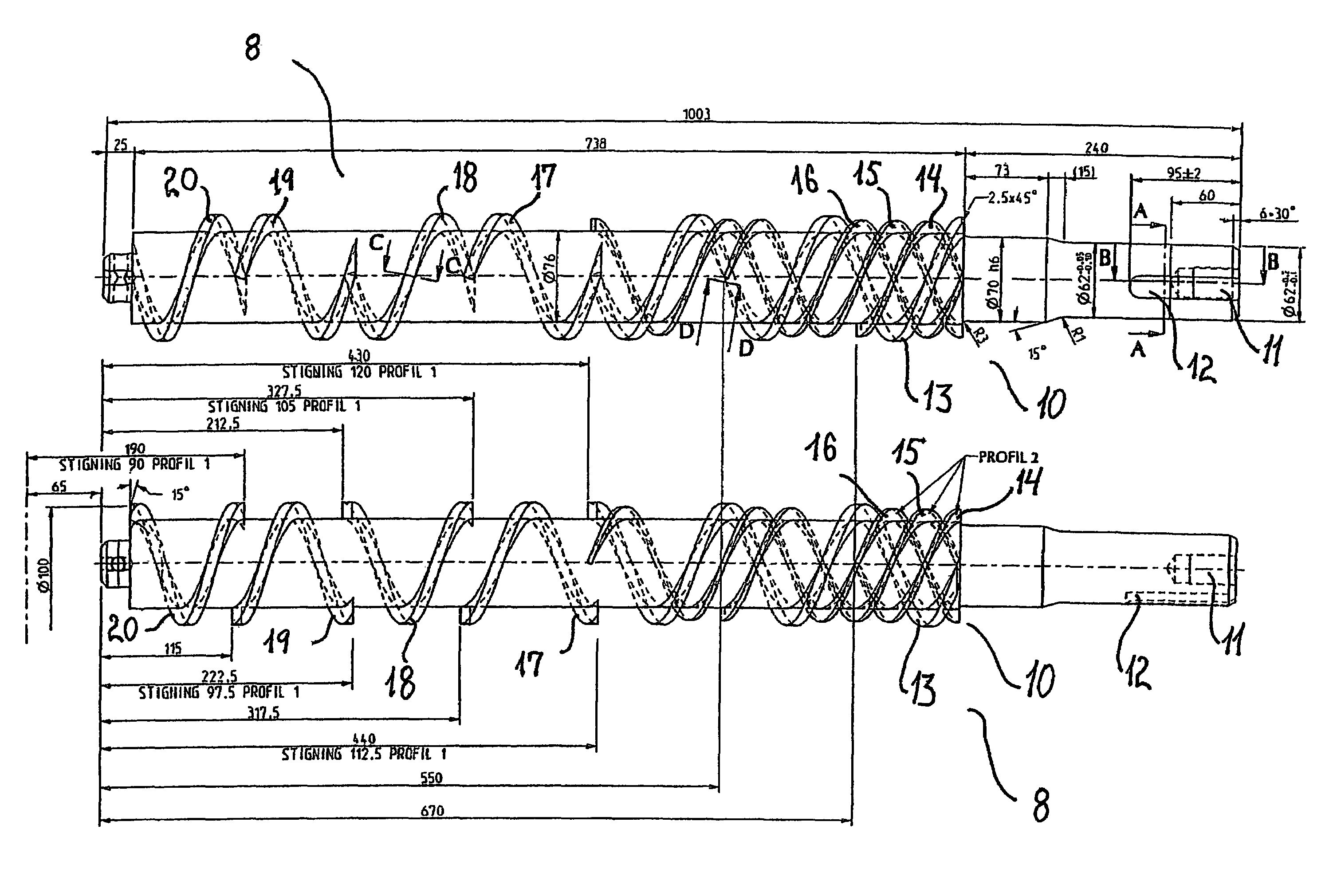
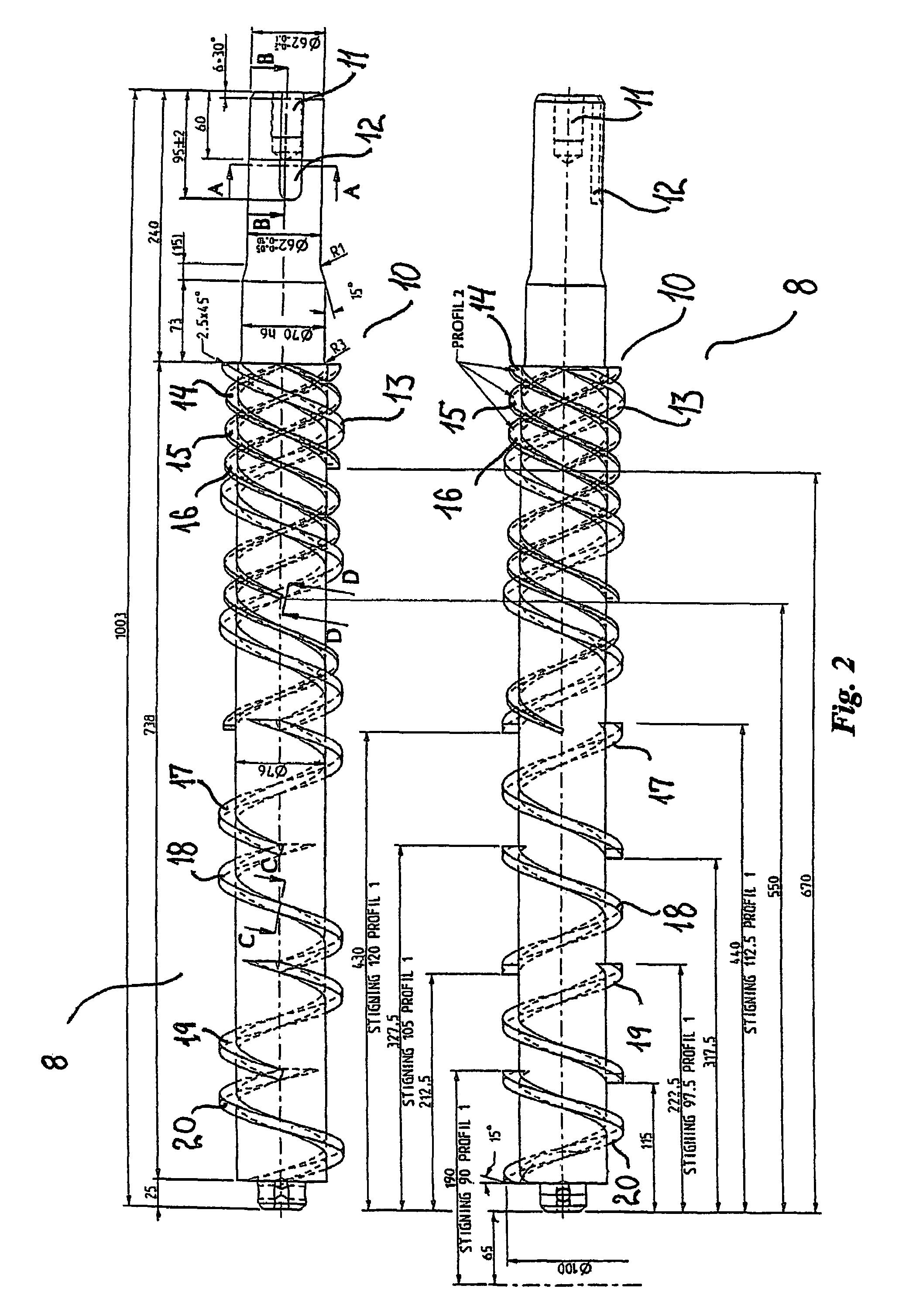
[0015]The screw flights are typically fastened to an inner closed core which may be of cylindrical shape but also of another shape, e.g. frusto-conical, in order to vary the open cross-sectional area and thereby the speed of conveyance. The outer edge of the screw flights will for the longest screw flights normally extend to a radius which is constant along the longitudinal axis of the conveyor screw so that the conveyor screw fits into a cylindrical cavity, but also this radius may be varied along the longitudinal axis so that the conveyor screw e.g. fits into a frusto-conical cavity for in this way to vary the open cross-sectional area as well as the surface area of the surface of the cavity with which the conveyed mass comes in contact during the conveyance. The latter can be an advantage if e.g. the heat transfer through the surface is to be increased near the outlet end of the conveyor screw.
[0016]In order to lower the necessary inlet pressure for a conveyance apparatus with the said conveyor screw, it is an advantage that said at least two screw flights extend over an inlet end part of the conveyor screw so that the radially shorter screw flights, e.g. 0,85-0,98 times the radius of the longer screw flight, increases the conveyance near the inlet end and thereby increases the inlet suction of the conveyance apparatus.
[0018]The at least two screw flights extending at a lower radial distance from the longitudinal axis, extend in a preferred embodiment from the inlet end part and in different longitudinal distances form the inlet end part so that the assisting conveyance, which is performed by these radially shorter screw flights, decreases gradually from the inlet end and that the mixing of the mass some distance inside the conveyance apparatus thereby is increased with an increased homogeneity of the mass as a result. The radially shorter screw flights perform preferably the conveyance of the warmer ice cream mass with a lower viscosity and as the temperature drops from the inlet end towards the outlet end the quantity of the ice cream mass with the lower viscosity is reduced and thereby the quantity which is to be conveyed by the radially shorter screw flights. The difference in the extension of the screw flights from the inlet end part amounts in a preferred embodiment of the invention to from 8% to 50%, preferably from 12% to 40% of the total length of the conveyor screw by which is understood the part of the conveyor screw which is in contact with the mass being conveyed.
[0019]It has appeared to be advantageous that the pitch of the screw flights at the inlet end of the conveyor screw is relatively high, i.e. 0.9 to 1.4, preferably 1.1 to 1.3 unlike the normal pitch of the screw flights of such conveyor screws of 0.5 to 1, where the pitch is given as the ratio of the length of one turn in the longitudinal direction of the conveyor screw and the outer diameter of the longest screw flights. With a high screw pitch, a higher conveyance length per rotation of the conveyor screw is achieved and the scraping frequency is reduced per unit length the mass is conveyed. The speed of rotation can thereby also be lower in order to conveyance a given volume of the mass.
[0023]It has further shown to be advantageous that the pitch of the screw flights is reduced along the longitudinal direction of the conveyor screw to 0.7 to 1, preferably 0.8 to 0.9 at an outlet end of the conveyor screw. Thereby, the pressure increases somewhat towards the outlet end, and the ice cream mass or other mass, which is conveyed by means of the conveyor screw, obtains a suitable pressure at the outlet end for feeding into the following manufacturing machines such as extruding apparatuses. A similar effect may, as mentioned previously, be achieved by increasing the diameter of the core of the conveyor screw but as to manufacture, it is preferred to reduce the pitch of the screw flights instead.
[0025]If the conveyor screw is made in such a way that the screw flights extending to the highest radial distance from the longitudinal axis progress discontinuously in the longitudinal direction so that a peripherally extending opening exists between these screw flights at least at one position along the longitudinal direction, it has been found that fluctuations in the discharge quantity per time unit may be reduced and actually completely eliminated. The use of openings in screw flights is known from an extruder, which is described in WO 00 / 44548. It has by the present invention been found to be suitable with from two to eight of such openings in the full length of the conveyor screw, preferably from three to six. Another way to estimate how many openings it is advantageous to provide, is an average distance in the longitudinal direction between the openings of from 1 to 4 times the outer diameter of the screw, preferably form 1.5 to 2.5. The effect of the openings is that the pressure difference between the pressure side and the suction side of the screw flights is equalized which has been found to give a more even pressure distribution in the mass. The high viscosity of the mass results in that the pressure differences in the conveyed mass builds up high local pressure gradients to a greater extent than for masses of low viscosity, as the mass not immediately flows due to the pressure gradient and thereby equalizes it.

Problems solved by technology

The result of the use of such a known conveyor screw freezer for the further cooling down is, however, not positive as, in order to carry out the scraping off and the conveyance of the ice cream mass, it is necessary to add such a quantity of power that the freezer will become inefficient due to the added scraping, kneading and pumping power, which results in a generation of heat in the ice cream mass.
Through-flow freezers, which work in this way, are known from the literature, see DE-A-39 18 268 and WO 97 / 26800, but are rarely used in practice as far as ordinary ice cream is concerned as it has been found that the process involves quite essential problems.
The higher viscosity of the ice cream in the subsequent through-flow freezer due to the lower temperature caused a number of problems.
The mechanical power is deposed in the ice cream mass which therefore must be cooled further and cause a higher power consumption for cooling, as well as a limitation of the capacity of the subsequent through-flow freezer.
In addition, the inlet pressure of the subsequent through-flow freezer must be high, in the order of 12-14 bar, in order for the ice cream mass to be fed to it, which poses heavy demands on pipes, gaskets etc. strains the preceding through-flow freezer, which must deliver the high pressure as well as reduces the quality of the product as the high pressure causes a lowering of the melting point of the ice cream mass which promotes the development of ice crystals in the ice cream mass and reduces the overrun of the ice cream.
Further, experiments showed that the discharge quantity per time unit for the subsequent through-flow freezer displayed fluctuations, which is inexpedient for the further manufacturing process for the ice cream mass, and that the degree of swelling decreased form inlet to outlet during creation of larger air pockets in the ice cream mass.

Method used


Image

  • Conveyor screw for use as surface scraper in cooling and freezing units
  • Conveyor screw for use as surface scraper in cooling and freezing units
  • Conveyor screw for use as surface scraper in cooling and freezing units

Examples


Embodiment Construction

[0039]The manufacturing plant for production of extruded ice cream products, as schematically illustrated in FIG. 1, comprises a preceding through-flow freezer 1, which, from a supply 2, is supplied with a “mix” passing a pump 3 and a mixing compartment 4 in which this mix is mixed with air from a compressed air source 5 in order to achieve an overrun of traditionally about 100%. This prepared ice cream substance is cooled down in the through-flow freezer 1 to a temperature below 0° C., such as from −2° C. to −10° C., which is completely normal for later division in portions and forming of the substance.

[0040]In connection with the invention, the cooled substance is conveyed further via a pipeline 6 through a subsequent through-flow freezer 7 for later extrusion at a temperature of −12 to −25° C. so that the cut ice bodies can be packed for directly transfer to the freezing storage. The subsequent through-flow freezer 7 is positively conveying, i.e. it comprises a conveyor screw 8 d...


PUM

PropertyMeasurementUnit
temperatureaaaaaaaaaa

Abstract

A conveyor screw for conveyance of high viscose masses and an apparatus with such a conveyor screw, preferably for production of an ice cream. Said crew having a plurality of screw flights, where at least two screw flights extend from an inlet end part of the conveyor screw and wherein the outer edges of the two screw flights extend in different radial distance from longitudinal axis. Whereby the radially shorter screw flight assists with the conveyance of a part of the mass without affecting the whole mass and especially without affecting the ice layer, which by use of the conveyor screw in a through-flow freezer is created on the inner wall of the freezing cylinder. Cooling the mass to a temperature of −15° C. or lower as preparation for extrusion of the mass for formation.

Description

[0001]The present relates to a conveyor screw for conveyance of high viscose masses and an apparatus with such a conveyor screw, preferably for production of an ice cream mass and more specific, a production where the material in shape of the so-called mix with a substantial content of air firstly is cooled down to an ordinary forming temperature of typical −5° C. and is then led further through a through-flow freezer with a scraping conveyor screw, wherein it is aimed to cool the mass to a temperature of −15° C. or lower as preparation for extrusion of the mass for forming of the final ice cream bodies for packing and final storage.BACKGROUND OF THE INVENTION[0002]By use of a through-flow freeze for this purpose, an ice layer is formed on the inner wall of the freezing cylinder of the through-flow freezer, which has to be scraped off by means of the conveyor screw that is rotating in the freezing cylinder and at the same time creates a positive conveyance of the ice cream mass thro...

Claims


Application Information

Patent Timeline
Patent Type & Authority Patents(United States)
IPC IPC(8): A23B9/12A23G9/04A23G9/14A23G9/16A23G9/20A23G9/22A23G9/28A23L3/36B29C48/03B29C48/65
CPCA23G9/045A23G9/14A23G9/16A23G9/20A23G9/224A23G9/285A23L3/361B29C47/60B29C47/625A23G9/228B29C47/0009B29C48/03B29C48/65
Inventor RASMUSSEN, HENRIK GULDMANN
Owner TETRA LAVAL HLDG & FINANCE SA
Why Eureka
Try Eureka