Transfer and insulation device for electrolysis

a technology of transfer and insulation, applied in the direction of manufacturing tools, electrical-based machining electrodes, machining electrodes, etc., can solve the problems of notched conductor rails, high manufacturing costs, and damage to tanks, and achieve the effects of convenient attachment, convenient gripping, and advantageous lifting and lowering

Active Publication Date: 2009-10-06
OUTOTEC OYJ
View PDF12 Cites 7 Cited by
  • Summary
  • Abstract
  • Description
  • Claims
  • Application Information

AI Technical Summary

Benefits of technology

[0013]Advantageously the transfer and insulation device is designed so that it is easy to grip by a transfer hook of the electrode transfer device or by a corresponding transfer element. The device includes a grip lug, and the anode is advantageously lifted and lowered without swinging, when it is gripped at said lug. Advantageously the device is placed so that the grip lug is oriented towards the center part of the anode, so that the transfer hooks of the transfer arrangement are easily attached at the lugs. The grip lug is provided with an inclined part that helps the crane transfer hook to slip in the right spot in the grip lug, so that the lifting of the electrode is carried out successfully. Separate transfer lugs conventionally made in anodes are replaced by grip lugs provided in the device according to the invention.
[0014]In order to avoid short circuits, adjacent anodes and cathodes must not get into contact in the tank. The distribution element of the device advantageously prevents the anodes and cathodes from touching each other in the tank, and it distributes the electrodes at even distances and at the same height in the tank. Thus it is unnecessary to provide notches in the conductor rail structure in order to ensure that the electrodes are placed equidistantly. When lowering an anode in the tank, in case of a possible erroneous movement in the sideways direction, the end of the suspension rod is prevented from touching the electroconductive rail or support element of the adjacent electrode, because the distribution element of the device first touches the tank wall and thus prevents the end from touching the rail. Remarkable savings in the expenses of the electrolytic process are achieved by using the transfer and insulation device according to the invention, and automatic transfer processes of the electrodes are made much easier. By means of the device according to the invention, a device made of one single piece is provided with several functions that earlier were replaced for example by notching the conductor rail structure and by providing the anodes with lifting lugs. Advantageously the device is designed so that when lowering a cathode beside an anode, any mutual contact between them is prevented.

Problems solved by technology

In connection with loading in the tank, separate loading elements approach the tank walls and the conductor rails resting on the tank together with their insulations, so that even small errors in the movements of a loading element may damage the tanks, the conductor rails or the insulations.
The manufacturing of a notched conductor rail, generally extending over the whole tank, is expensive.
Also the manufacturing of notched electrodes is expensive, and when immersing them in the tank, they must be lowered at exactly the right spot with respect to the conductor rail, when seen in the transversal direction of the tank.
A possible heat extension of the conductor rail may cause problems while using an automatic crane, because when replacing electrodes, the heat extension of a conductor rail may shift the electrode positions, i.e. the notches.
If a notched conductor rail is used, the electrode distribution cannot be changed without replacing all conductor rails and insulation rails.
This makes cleaning, particularly mechanized cleaning, more difficult.
A notched rail must be made relatively thin, wherefore it generally becomes fairly weak and short-lived.

Method used


Image

  • Transfer and insulation device for electrolysis
  • Transfer and insulation device for electrolysis
  • Transfer and insulation device for electrolysis

Examples


Embodiment Construction

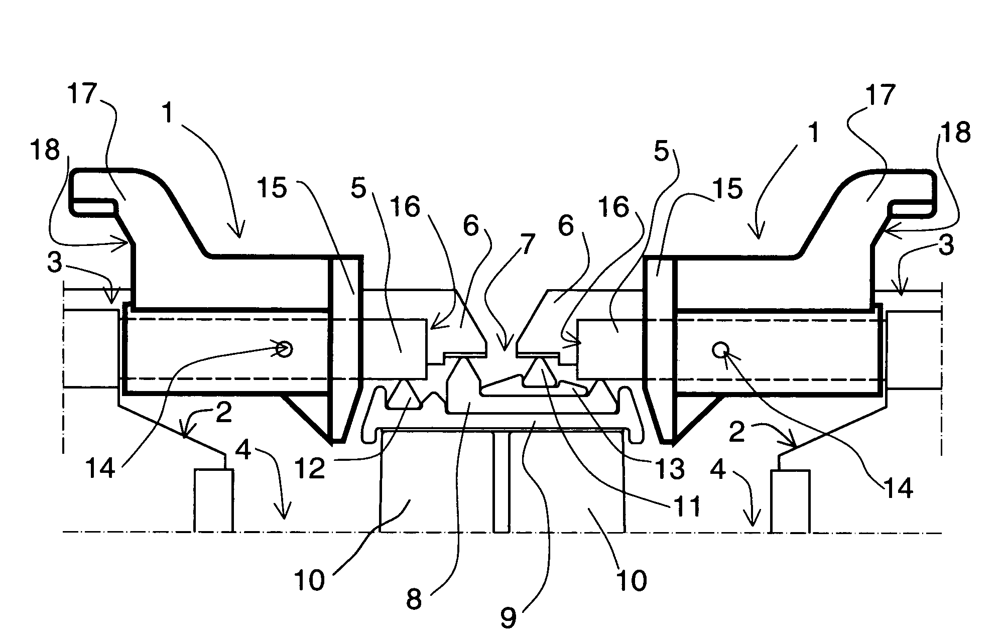
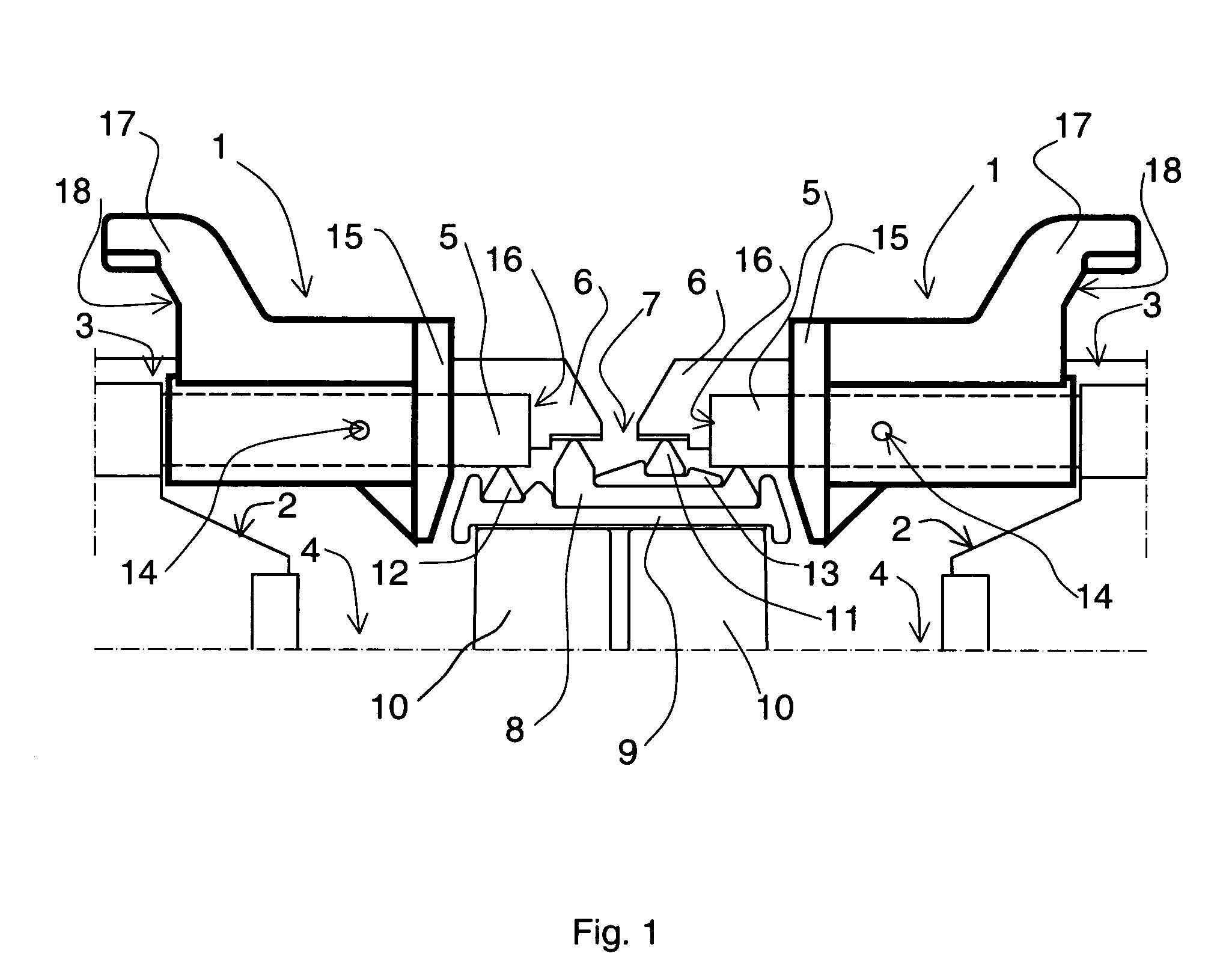
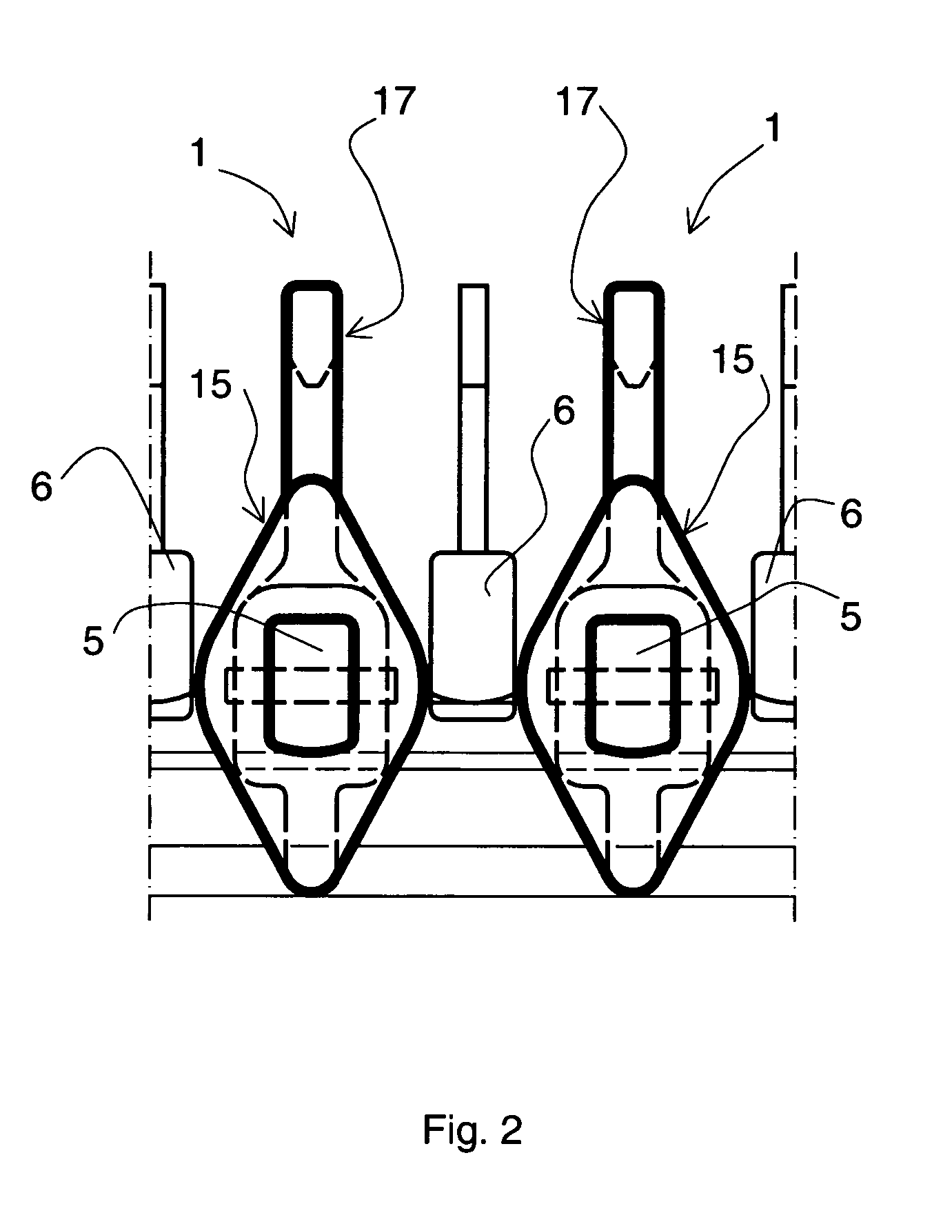
[0018]According to FIG. 1, the anodes 2 and cathodes 3 are lowered into electrolytic tanks 4, of which only two adjacent tanks are illustrated. In reality, an electrolytic process includes a large number of adjacent tanks, where similar structures are repeated. According to the drawing, the anodes 2 and cathodes 3 are placed in the tank 4 in succession, in an alternating order, in the lengthwise direction of the tank. The drawing shows first an anode at the front, and behind the anode, a cathode that is located further up. Both the anodes and the cathodes are suspended, by means of their suspension rods 5 and 6, in conductor rail structures 7 placed on top of the walls 10 of the electrolytic tank 4. The conductor rail structure comprises a conductor rail 8 extending over the whole length of the tank in order to electrically connect the anode and the cathode of adjacent tanks, and an insulation sheet 9 of the same length as the tank, placed between the conductor rail and the wall 10....


PUM

PropertyMeasurementUnit
electroconductiveaaaaaaaaaa
currentaaaaaaaaaa
movementsaaaaaaaaaa

Abstract

The invention relates to a transfer and insulation device (1) for electrically insulating electrodes, particularly anodes (2) and cathodes (3), used in the electrolytic cleaning of metals, from each other in an electrolytic tank (4), for distributing the electrodes as they are hanging in the electrolytic tank and for enabling the electrodes to be transferred, said transfer and insulation device (1) being made of one single piece.

Description

CROSS-REFERENCE TO RELATED APPLICATION[0001]This is a U.S. national phase patent application of the PCT application No. PCT / F103 / 00215 filed on Mar. 20, 2003 that claims priority from Finish patent application no. 20020635 filed on Apr. 3, 2002, both of which are incorporated by reference.FIELD OF THE INVENTION[0002]The invention relates to a transfer and insulation device, made from one single piece, for electrically insulating electrodes, particularly anodes and cathodes, used in the electrolytic cleaning of metals in the electrolytic tank, for distributing electrodes as they are hanging in the electrolytic tank and for enabling the electrodes to be transferred.BACKGROUND OF THE INVENTION[0003]In an electrolytic plant meant for electrolytically cleaning metals such as copper, zinc and nickel, there is typically a large number of electrolytic tanks that are in groups connected in series, so that the anode of the preceding tank is electrically connected to the cathode of the next ta...

Claims


Application Information

Patent Timeline
Patent Type & Authority Patents(United States)
IPC IPC(8): B23H3/04C25C7/04C25F7/00C25C7/06
CPCC25C7/06C25C7/04
Inventor KIVISTO, TUOMOMARTTILA, TOM
Owner OUTOTEC OYJ
Why Eureka
Try Eureka