Light-emitting diode
a technology of light-emitting diodes and diodes, which is applied in the direction of semiconductor devices, display means, instruments, etc., can solve the problems of difficult to obtain a light-emitting diode of high luminance, and achieve the effect of narrow directivity and high luminan
- Summary
- Abstract
- Description
- Claims
- Application Information
AI Technical Summary
Benefits of technology
Problems solved by technology
Method used
Image
Examples
embodiment 1
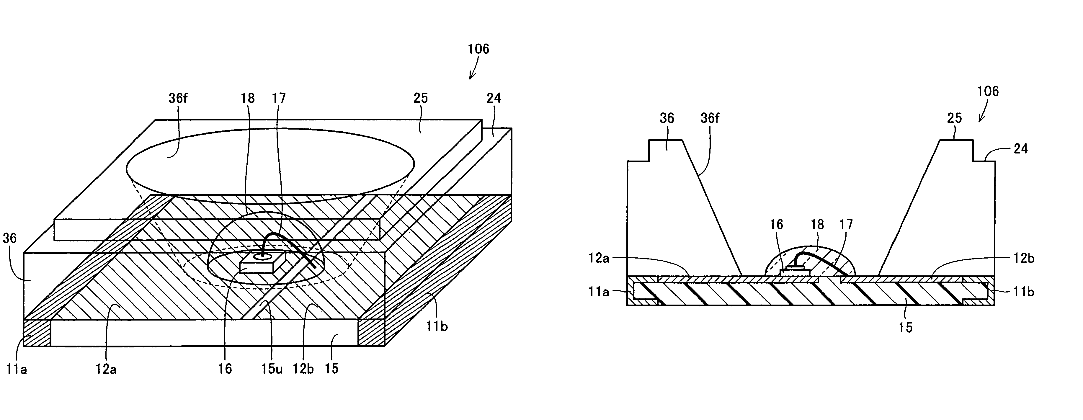
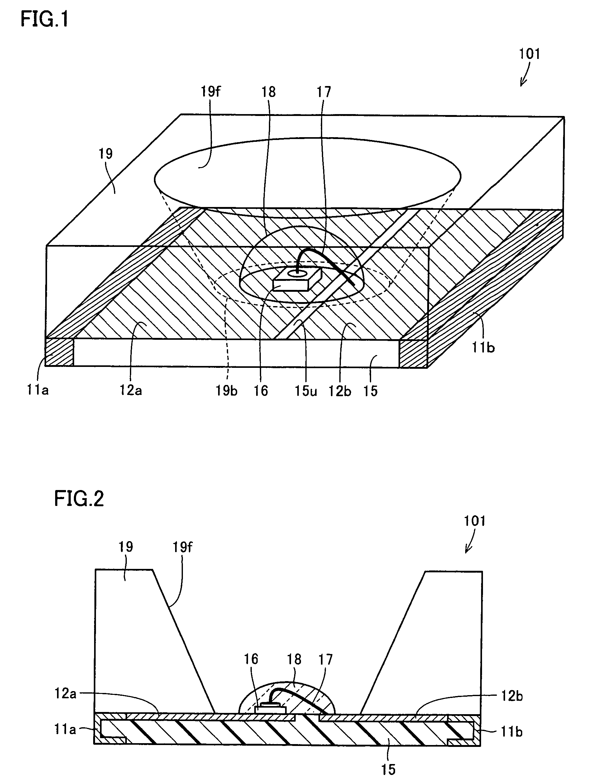
[0038]A light-emitting diode according to Embodiment 1 of the present invention will be described with reference to FIGS. 1 and 2. FIGS. 1 and 2 show a perspective view and a cross-sectional view of a light-emitting diode 101, respectively. Light-emitting diode 101 includes a substrate 15 having a main surface 15u, a light-emitting diode device 16 arranged on main surface 15u, a metal line 17 arranged to electrically connect light-emitting diode device 16 and main surface 15u to each other, a translucent sealing resin portion 18 sealing light-emitting diode device 16 and metal line 17 so that light-emitting diode device 16 and metal line 17 are implemented as an independent convex portion projecting from main surface 15u, and a reflector 19 arranged on main surface 15u so as to surround an outer perimeter of sealing resin portion 18 with an inclined surface 19f at a distance from the outer perimeter. Substrate 15 is in a rectangular shape, and terminal electrode portions 11a, 11b ar...
embodiment 2
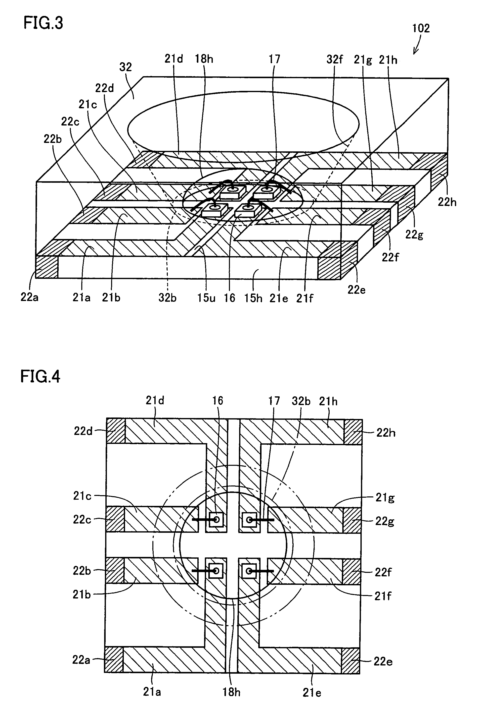
[0043]A light-emitting diode according to Embodiment 2 of the present invention will be described with reference to FIGS. 3 and 4. A light-emitting diode 102 is of a type implemented by collectively sealing a plurality of light-emitting diode devices 16 with a resin. FIG. 3 shows a perspective view of light-emitting diode 102, and FIG. 4 shows a plan view of the same in a state before the reflector is attached. FIG. 4 shows upper and lower contours of a through hole in the reflector with chain double dotted lines. As shown in FIG. 3, light-emitting diode 102 includes a substrate 15h having main surface 15u, a plurality of light-emitting diode devices 16 arranged on main surface 15u, a plurality of metal lines 17 arranged to electrically connect the plurality of light-emitting diode devices 16 to main surface 15u respectively, a translucent sealing resin portion 18h collectively sealing the plurality of light-emitting diode devices 16 and the plurality of metal lines 17 so that the p...
embodiment 3
[0045]A light-emitting diode according to Embodiment 3 of the present invention will be described with reference to FIGS. 5 and 6. A light-emitting diode 103 is of a type implemented by individually sealing a plurality of light-emitting diode devices 16 with a resin. FIGS. 5 and 6 show an enlarged perspective view and an enlarged plan view of a central portion of light-emitting diode 103, respectively. FIG. 6 shows a state after the reflector is attached. Light-emitting diode 103 includes a substrate having main surface 15u, a plurality of light-emitting diode devices 16 arranged on main surface 15u, a plurality of metal lines 17 arranged to electrically connect the plurality of light-emitting diode devices 16 to main surface 15u respectively, a plurality of translucent sealing resin portions 18i individually sealing respective sets of the plurality of light-emitting diode devices 16 and the plurality of metal lines 17 so that the respective sets of the plurality of light-emitting d...
PUM
 Abstract
Description
Claims
Application Information
 - R&D
- Intellectual Property
- Life Sciences
- Materials
- Tech Scout
- Unparalleled Data Quality
- Higher Quality Content
- 60% Fewer Hallucinations
Browse by: Latest US Patents, China's latest patents, Technical Efficacy Thesaurus, Application Domain, Technology Topic, Popular Technical Reports.
© 2025 PatSnap. All rights reserved.Legal|Privacy policy|Modern Slavery Act Transparency Statement|Sitemap|About US| Contact US: help@patsnap.com


