System and method for image matting

a technology of image matting and system, applied in the field of image editing, can solve the problems of general under-constrained matting, and achieve the effect of minimizing errors

Inactive Publication Date: 2009-10-06
MITSUBISHI ELECTRIC RES LAB INC
View PDF2 Cites 45 Cited by
  • Summary
  • Abstract
  • Description
  • Claims
  • Application Information

AI Technical Summary

Problems solved by technology

Matting is generally under-constrained, because not enough information is obtained when the images are acquired.

Method used


Image

  • System and method for image matting
  • System and method for image matting
  • System and method for image matting

Examples


Embodiment Construction

[0036]System Overview

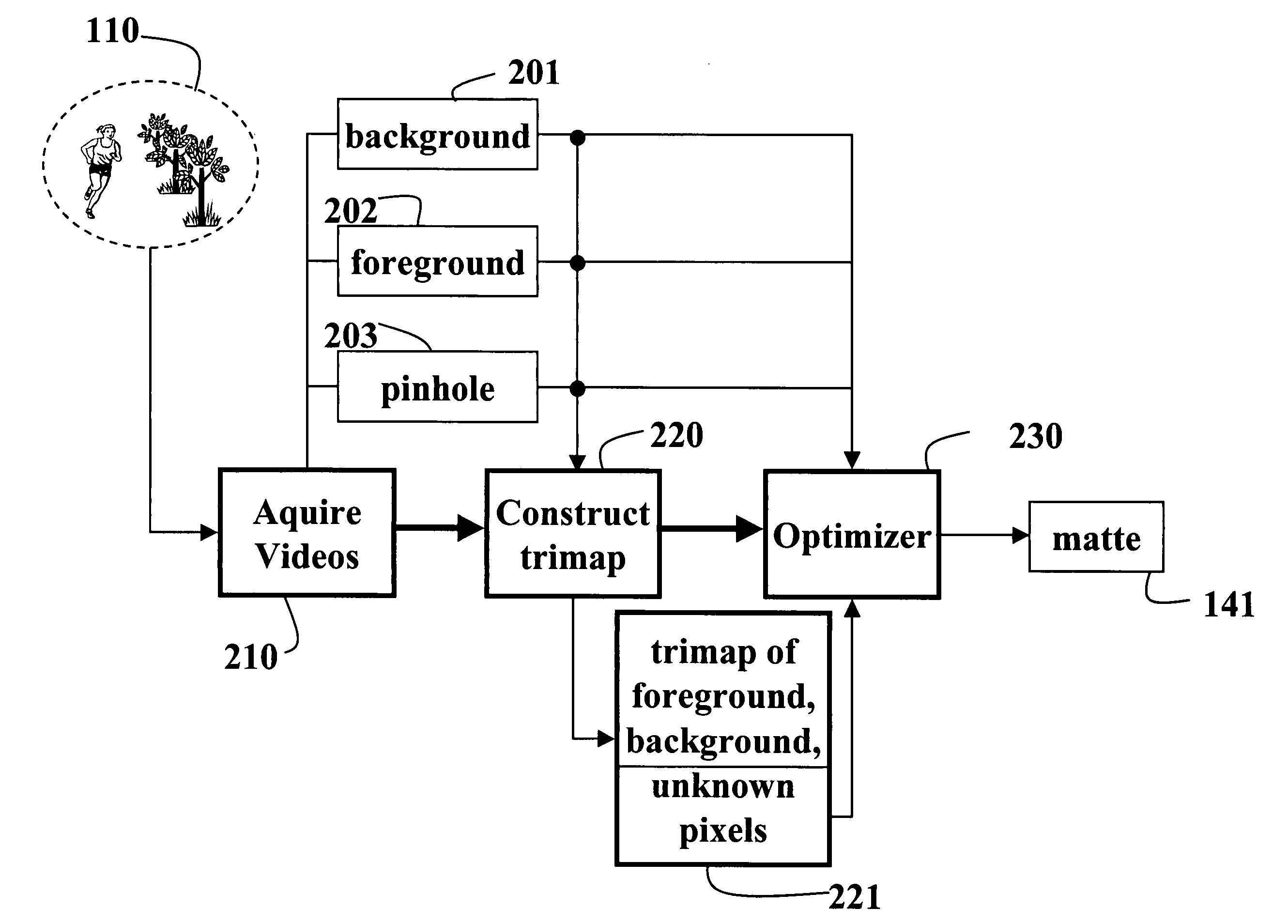
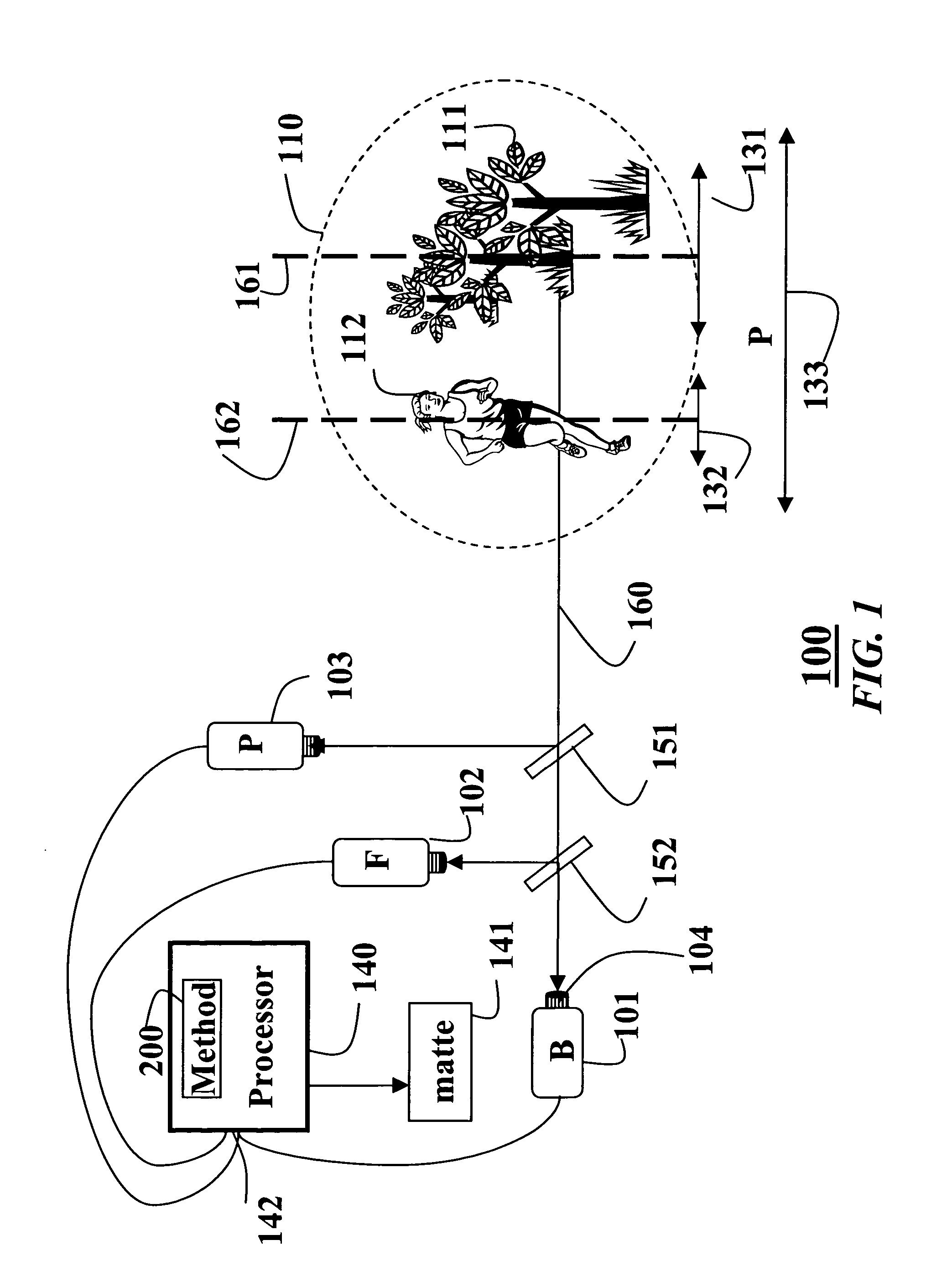
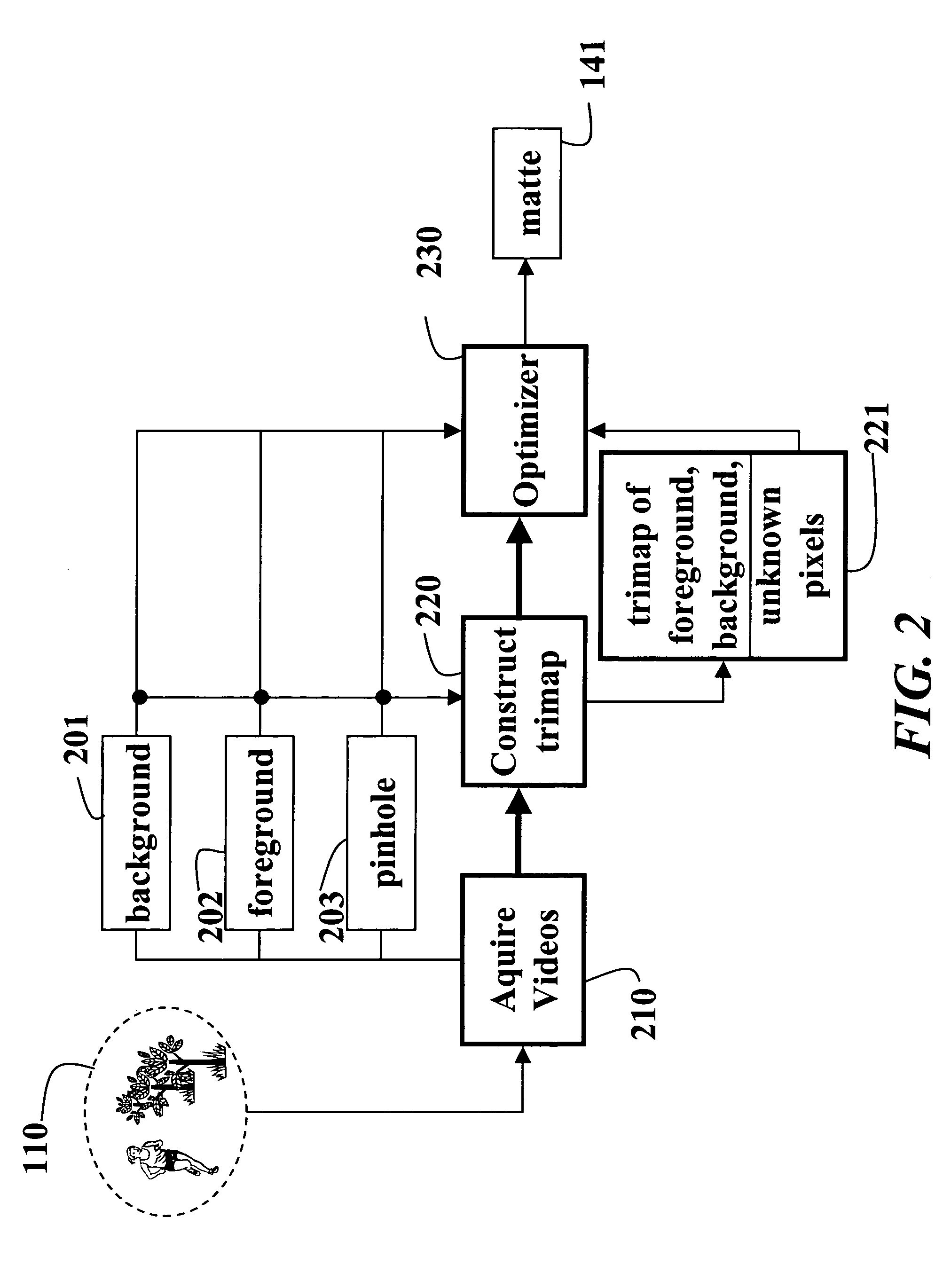
[0037]FIGS. 1 and 2 shows a system 100 and method 200 according to our invention for automatically extracting a matte 141 from images acquired of a scene 110 including a background region (B) 111 having a background depth of field 131, and a foreground region (F) 112 having a foreground depth of field 132. These can be a natural, real word indoor or outdoor scene illuminated only by ambient light.

[0038]Cameras

[0039]The images are acquired 210 by a background camera 101, a foreground camera 102, and a pinhole camera (P) 103. The three cameras 101-103 are aligned on a single optical axis 160, sharing a single virtual center of projection, using first and second beam splitters 151-152. Therefore, all cameras have an identical point of view of the scene 110. The cameras are synchronized and connected to a processor 140.

[0040]The foreground and background cameras have relatively large apertures, resulting in small, non-overlapping depths of fields 131 and 132. That i...


PUM


Abstract

A method compresses a set of correlated signals by first converting each signal to a sequence of integers, which are further organized as a set of bit-planes. An inverse accumulator is applied to each bit-plane to produce a bit-plane of shifted bits, which are permuted according to a predetermined permutation to produce bit-planes of permuted bits. Each bit-plane of permuted bits is partitioned into a set of blocks of bits. Syndrome bits are generated for each block of bits according to a rate-adaptive base code. Subsequently, the syndrome bits are decompressed in a decoder to recover the original correlated signals.

Description

FIELD OF THE INVENTION[0001]This invention relates generally to image editing, and more particularly to matting.BACKGROUND OF THE INVENTION[0002]Matting and compositing are frequently used in image editing, 3D photography, and film production. Matting separates a foreground region from an input image by estimating a color F and an opacity α for each pixel in the image. Compositing blends the extracted foreground into an output image, using the matte, to represent a novel scene.[0003]The opacity measures a ‘coverage’ of the foreground region, due to either partial spatial coverage or partial temporal coverage, i.e., motion blur. The set of all opacity values is called the alpha matte, the alpha channel, simply a matte.[0004]Matting is described generally by Smith et al., “Blue screen matting, “Proceedings of the 23rd annual conference on Computer graphics and interactive techniques,” ACM Press, pp. 259-268, and U.S. Pat. No. 4,100,569, “Comprehensive electronic compositing system,” i...

Claims


Application Information

Patent Timeline
Patent Type & Authority Patents(United States)
IPC IPC(8): G06K9/34
CPCH04N5/272
Inventor MCGUIRE, MORGANMATUSIK, WOJCIECHPFISTER, HANSPETERHUGHES, JOHN F.DURAND, FREDO
Owner MITSUBISHI ELECTRIC RES LAB INC
Why Eureka
Try Eureka