
Asynchronous copy protection detector

Inactive Publication Date: 2009-10-06
INTERDIGITAL CE PATENT HLDG
View PDF9 Cites 0 Cited by
  • Summary
  • Abstract
  • Description
  • Claims
  • Application Information

AI Technical Summary

Problems solved by technology

When video information including such pulses is copied, the pulses cause synchronization problems to occur in the resultant copy.
However, when the detection of pseudo-synchronization pulses is required in a video system lacking the aforementioned type of synchronization circuitry, the cost of adding such circuitry can be prohibitive.

Method used


Image

  • Asynchronous copy protection detector
  • Asynchronous copy protection detector
  • Asynchronous copy protection detector

Examples


Embodiment Construction

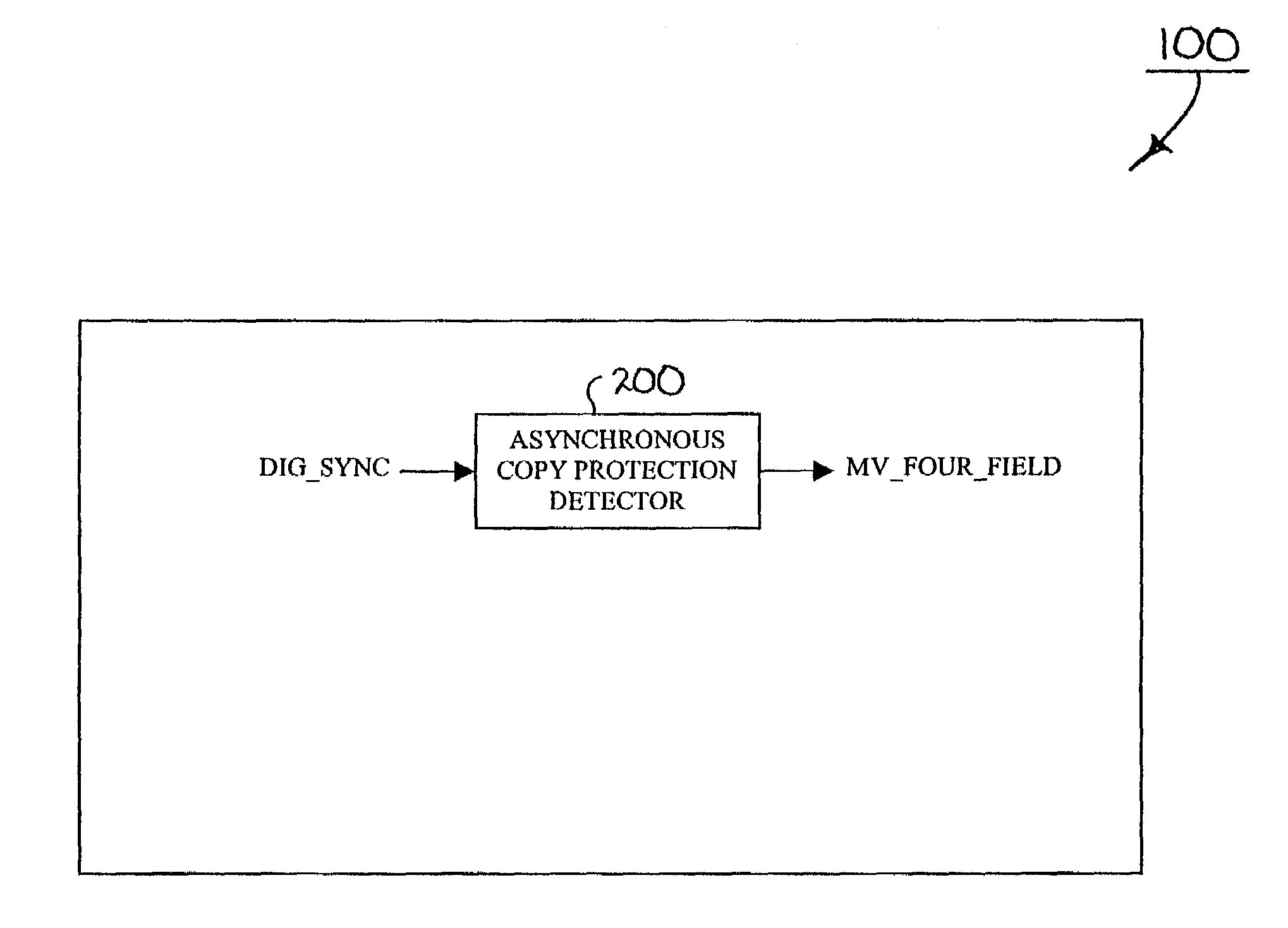
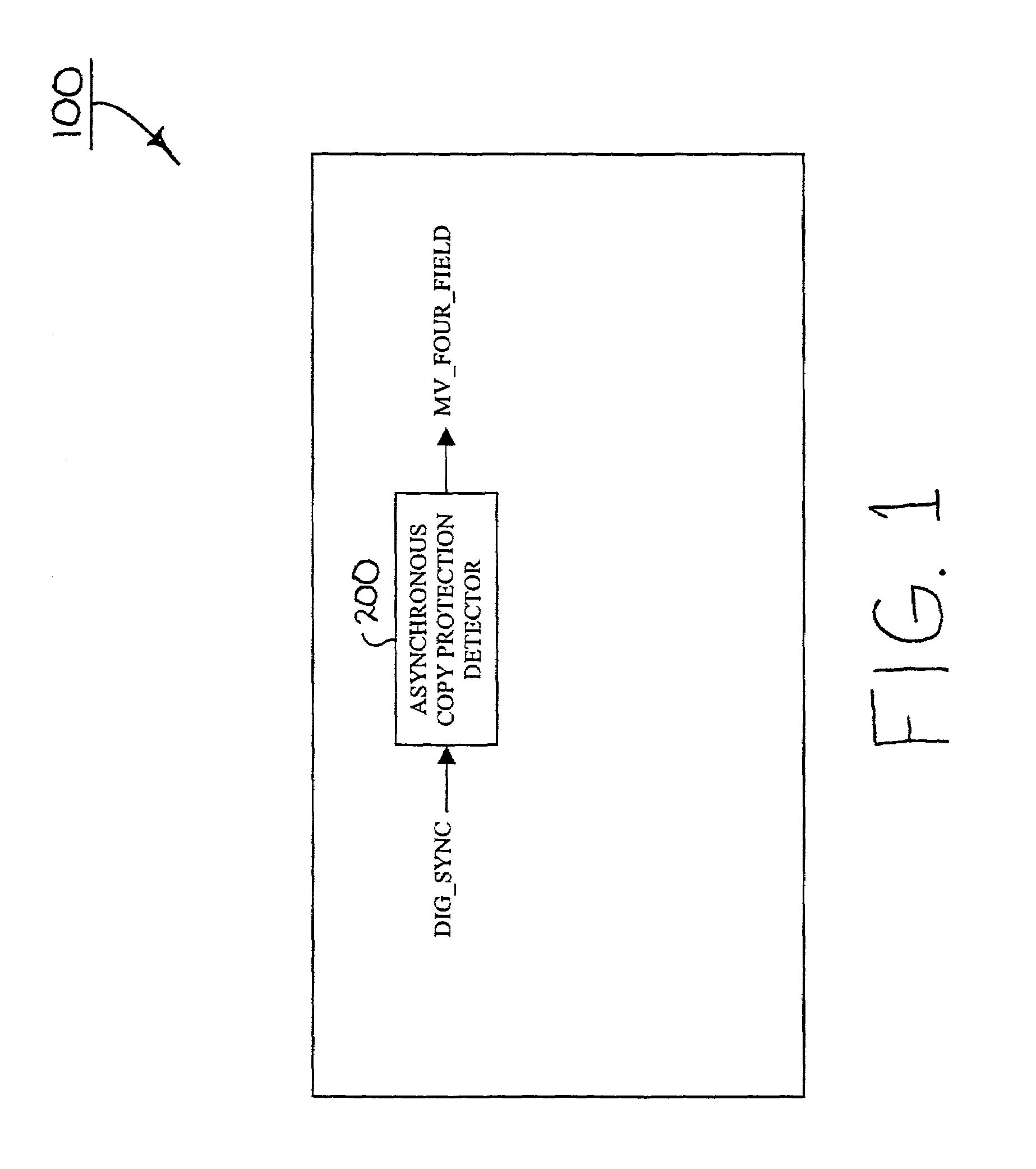
[0018]Referring now to the drawings, and more particularly to FIG. 1, a diagram of an exemplary video system 100 including an asynchronous copy protection detector 200 according to principles of the present invention is shown. Video system 100 of FIG. 1 may be embodied, for example, as a television signal receiver, a set-top box, a video cassette recorder (“VCR”), a digital versatile disk (“DVD”) player, a video game box, a personal video recorder (“PVR”) or any other system having a video processing function.

[0019]In FIG. 1, video system 100 is operative to receive a video signal from an external source (not shown), and extract therefrom a composite synchronization signal. Video system 100 includes asynchronous copy protection detector 200 for receiving and processing the composite synchronization signal, DIG_SYNC, in order to detect therein the presence of pseudo-synchronization pulses. As previously indicated herein, such pseudo-synchronization pulses are often encoded in video s...


PUM


Abstract

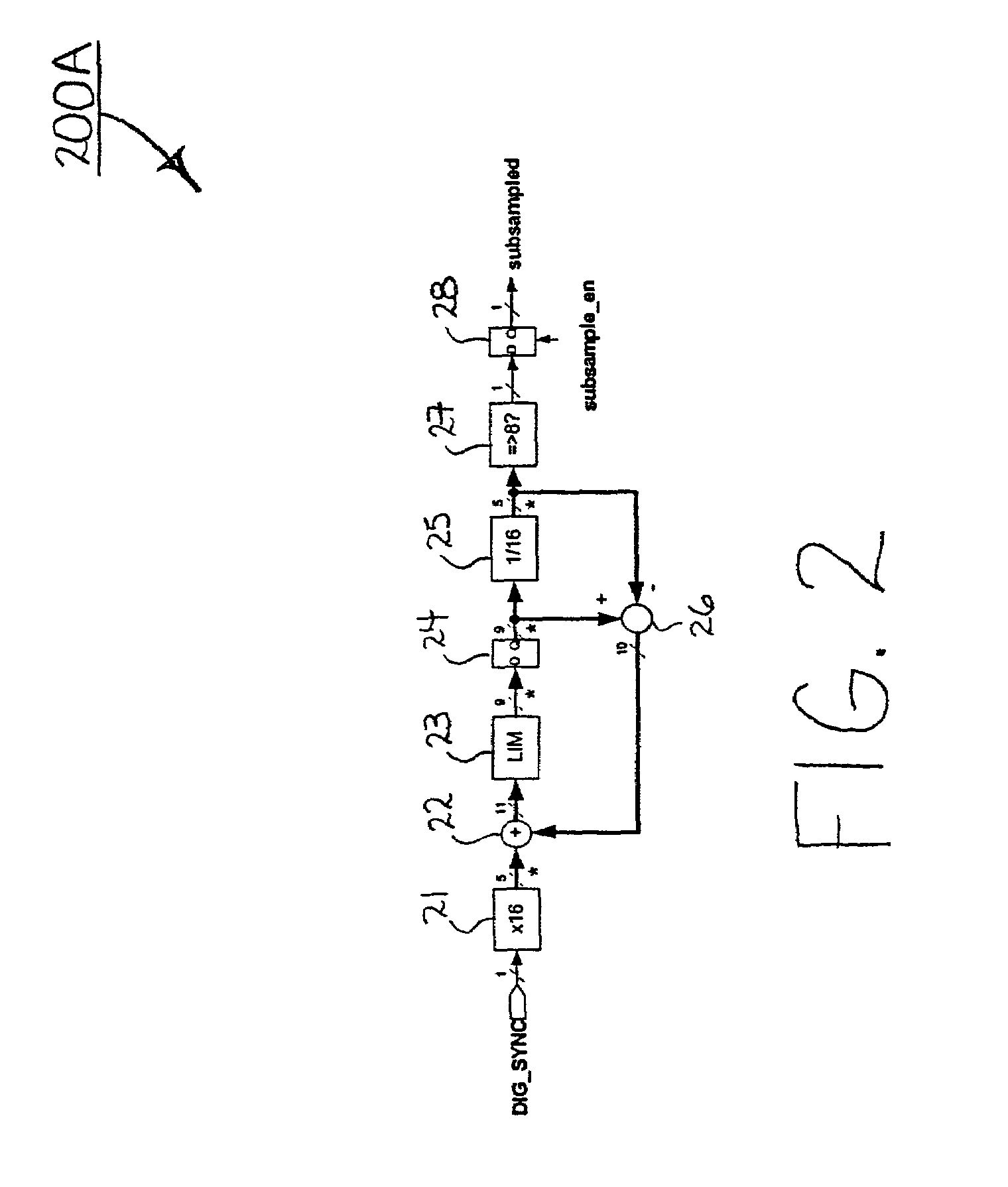
A video system (100) includes detection circuitry (200A-200C) operative to detect pseudo-synchronization pulses within a composite synchronization signal in dependence upon at least one timing signal. Timing circuitry (200D-200F) is operative to generate the at least one timing signal without utilizing synchronization information within the composite synchronization signal.

Description

[0001]This application claims priority to and all benefits accruing from a provisional application filed in the United States Patent and Trademark Office on Dec. 14, 2001, and there assigned Ser. No. 60 / 340,555.BACKGROUND OF THE INVENTION[0002]1. Field of the Invention[0003]The present invention generally relates to video systems, and more particularly, to an asynchronous copy protection detector for use in such video systems that is capable of, among other things, detecting the presence of pseudo-synchronization pulses in video signals without utilizing horizontal and / or vertical synchronization signals.[0004]2. Background Information[0005]Copy protection techniques are often utilized in the video industry to prevent the production of unauthorized video copies. One such copy protection technique involves inserting pseudo-synchronization pulses on certain lines of each video field. When video information including such pulses is copied, the pulses cause synchronization problems to o...

Claims


Application Information

Patent Timeline
IPC IPC(8): H04N7/00H04N5/91H04N7/087G11B20/00G11B23/28H04N5/913
CPCG11B20/00086G11B20/00615H04N5/913H04N2005/91314G11B23/28H04N5/91
Inventor RUMREICH, MARK FRANCISHAGUE, JOHN ALAN
Owner INTERDIGITAL CE PATENT HLDG
Learn More