Method and machine for determining a space coordinate of a measurement point on a measurement object

a technology of space coordinates and measuring objects, applied in the direction of electrical/magnetic measuring arrangements, compasses, program control, etc., can solve the problems of measurement errors, manufacturing tolerances, positional deviations of the probe head, etc., to achieve high synchronicity, high accuracy, and simple and cost-effective production

Active Publication Date: 2009-10-06
CARL ZEISS IND MESSTECHN GMBH
View PDF19 Cites 15 Cited by
  • Summary
  • Abstract
  • Description
  • Claims
  • Application Information

AI Technical Summary

Benefits of technology

[0011]Accordingly, a common regulator is used which generates the setpoint values (either in digital form or as analog control signals) for the two drives. In other words, the common regulator receives an actual value or an actual signal on the input side, which is equally representative of the kinematic state of the two drives. The common regulator can therefore actuate the two drives essentially in the same way. Furthermore, the use of a common regulator allows very simple and cost-effective production with relatively few components and little outlay for setup and adjustment work. Yet on the other hand, the common regulator generates a separate setpoint value for each of the drives, so that the two drives can be operated with minor differences despite the fundamental synchronism. In this way, the travel movements of the two supports can be controlled individually—within certain limits—in order to compensate for tolerances in the respective guides and between the drives.
[0035]This configuration is particularly simple and cost-effective to produce, and it leads to control without constraining forces in the case of coordinate measuring machines with very rigid coupling of the two supports.

Problems solved by technology

Measurement errors may have various causes.
One cause of error is due to manufacturing tolerances in the guides of the coordinate measuring instrument as well as elastic deformations of the coordinate measuring instrument, as a function of the gravitational moment which the probe head exerts on the displacement mechanism in its respective travel position.
Further causes of error may be positional deviations of the probe head, which arise because of and / or during the travel movements.
For coordinate measuring machines in portal or gantry design (i.e. coordinate measuring machines having a movable bridge on two mutually separated supports movable parallel to one another), measurement errors may also occur owing to lack of synchronicity in the travel movements of the two supports.
This leads to measurement errors both in the Y direction and in a second orthogonal direction (typically the X axis).
Another cause of error for coordinate measuring machines in portal or gantry design may be deformations, which arise because the two parallel supports are moved under constraint, i.e. the drive forces work against the existing linear guides.
Furthermore, such a situation also leads to increased wear.

Method used


Image

  • Method and machine for determining a space coordinate of a measurement point on a measurement object
  • Method and machine for determining a space coordinate of a measurement point on a measurement object
  • Method and machine for determining a space coordinate of a measurement point on a measurement object

Examples


Embodiment Construction

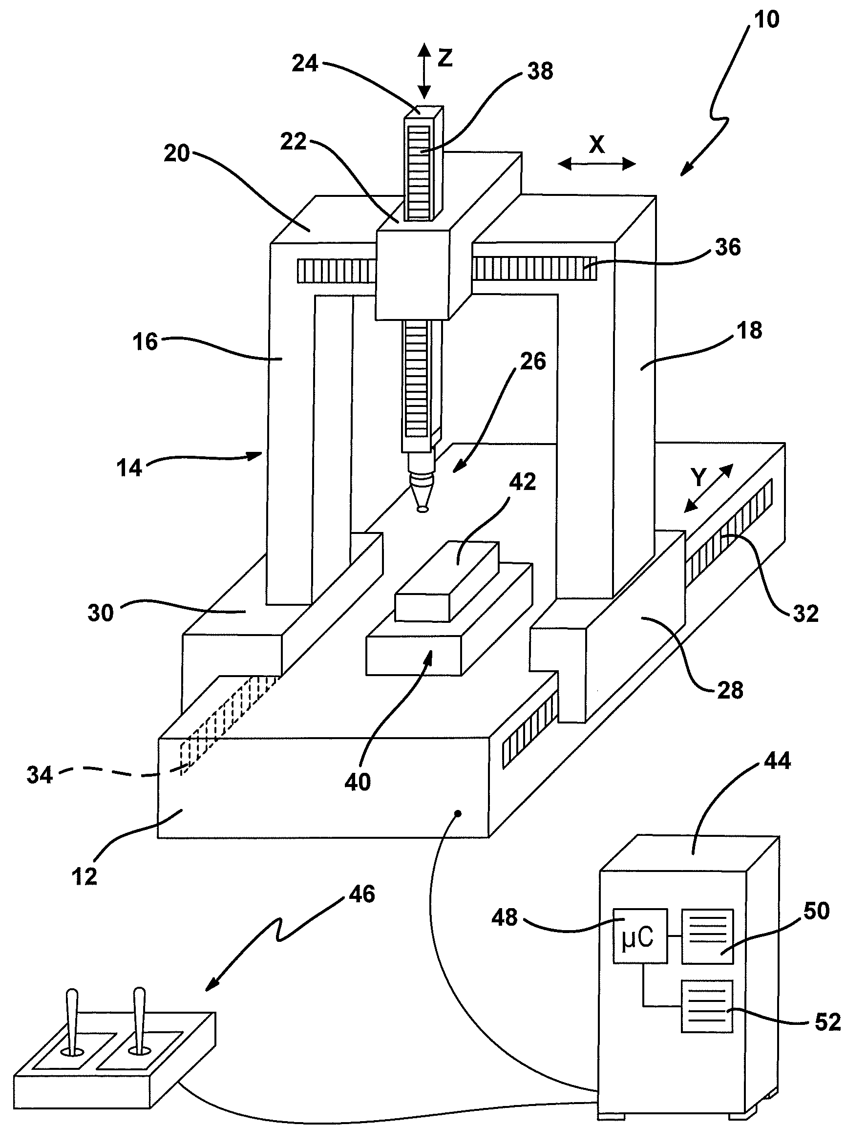
[0046]In FIG. 1, an exemplary embodiment of the new coordinate measuring machine is denoted overall by reference numeral 10.

[0047]The coordinate measuring machine 10 has a base 12, on which a portal 14 is arranged so that it can be displaced in the longitudinal direction (Y direction). The portal 14 has two portal feet (more generally: supports) 16, 18, which are connected by a bridge 20 at their other ends. A carriage 22, which can be displaced along the bridge, i.e. in a space direction (X direction) connecting the two portal feet 16, 18, is placed on the bridge 20. A ram 24, which can be displaced in a third space direction (Z direction) perpendicular to the first and second space directions, is arranged on the carriage 22. The three space directions X, Y and Z are preferably orthogonal to one another, although this is not absolutely necessary for the present invention.

[0048]A probe head 26, on which a stylus (not referred to in further detail) is arranged, is fastened on the low...


PUM


Abstract

For determining a space coordinate of a measurement point on a measuring object, the measurement point is approached with a probe head arranged on a displacement mechanism having at least two supports movable parallel to one another. Each support is moved by its own drive. The space coordinate of the measurement point is determined as a function of the respective displacement position of the supports. The two drives are controlled by a common regulator.

Description

CROSS REFERENCES TO RELATED APPLICATIONS[0001]This application is a continuation of international patent application PCT / EP2006 / 000062, filed on Jan. 5, 2006 designating the U.S., which international patent application has been published in German language as WO 2006 / 077017 A1 and claims priority from German patent application DE 10 2005 003 322.9, filed on Jan. 18, 2005. The entire contents of these priority applications are incorporated herein by reference.BACKGROUND OF THE INVENTION[0002]The present invention relates to a method and a machine for determining a space coordinate of a measurement point on a measuring object. More particularly, the invention relates to a method and a coordinate measuring machine, wherein a probe head is moved by means of a displacement mechanism comprising a first and a second support each driven from a separate drive.[0003]Generally, the space coordinates of a measurement point are determined by approaching the measurement point with a movable probe...

Claims


Application Information

Patent Timeline
Patent Type & Authority Patents(United States)
IPC IPC(8): G01B21/04
CPCG01B21/042G05B19/231G05B2219/42334G05B2219/37193
Inventor GRUPP, GUENTER
Owner CARL ZEISS IND MESSTECHN GMBH
Why Eureka
Try Eureka