Finned brake duct to divert cooling air to a vehicle brake system

a technology of brake ducts and cooling air, which is applied in the direction of brake systems, brake discs, fluid actuated brakes, etc., can solve the problems of difficult installation, difficult to provide sufficient targeted cooling air, and complicate the vehicle assembly process, so as to achieve the effect of simplifying manufacturing and installation

Inactive Publication Date: 2009-10-13
HONDA MOTOR CO LTD
View PDF14 Cites 25 Cited by
  • Summary
  • Abstract
  • Description
  • Claims
  • Application Information

AI Technical Summary

Benefits of technology

[0007]The present invention is directed toward an assembly that reliably directs a stream of cooling air to the front brake assembly of a motor vehicle. The present invention is further directed toward an assembly that accommodates changes in vehicle design, and that is adapted for implementation in limited-space installations. Finally, assembly of the present invention permits simplified manufacture and installation, including assembly independent of the front brake assembly.

Problems solved by technology

However, for heat generating components that are disposed external to the engine compartment, providing sufficient targeted cooling air is problematic.
These problems are the result of the severe space limitations for a cooling air duct, as well as by the swirling airflow inherent in a location external to the engine compartment or other confined space.
Such known structures typically include straight pipes that have an outlet attached directly to the brake assembly and, as such, are difficult to install and complicate the vehicle assembly process as they must be installed after the brake assembly is in place.

Method used


Image

  • Finned brake duct to divert cooling air to a vehicle brake system
  • Finned brake duct to divert cooling air to a vehicle brake system
  • Finned brake duct to divert cooling air to a vehicle brake system

Examples


Embodiment Construction

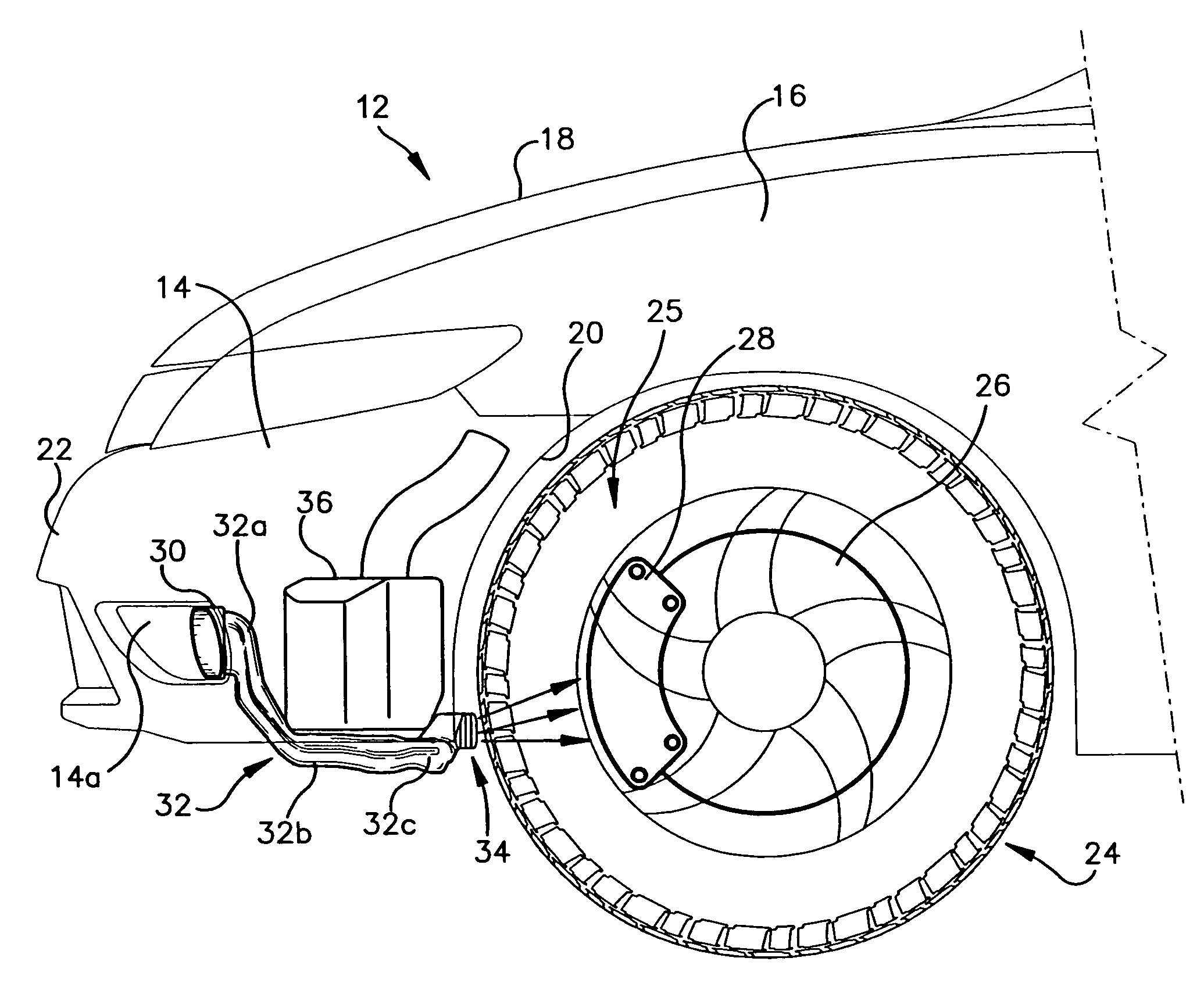
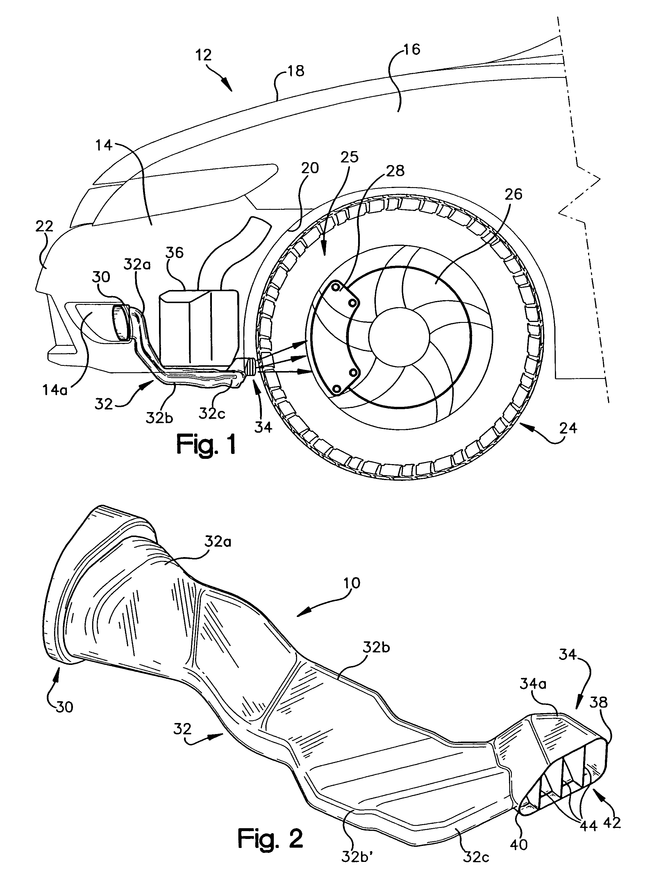
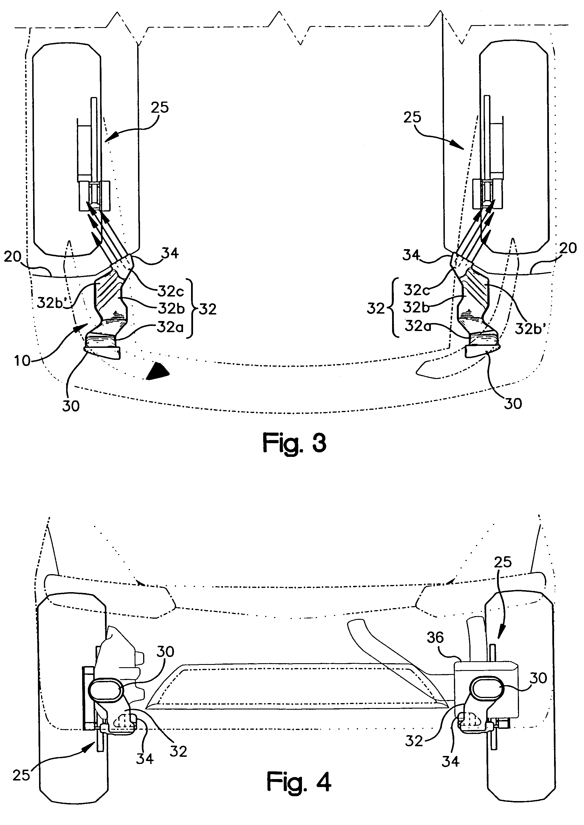
[0019]With reference to FIGS. 1 and 2, a finned brake duct assembly 10 according to the present invention is illustrated. In FIG. 1 the brake duct assembly 10 is shown disposed within a representative vehicle 12, which includes a front facia 14, a front fender 16, a hood 18, and a wheel well liner 20. The front facia 14, which may be molded from a plastic material, preferably includes a front bumper 22 and serves to provide a clean, aesthetically pleasing appearance to the lower front end and lower front corners of vehicle 12. A front wheel assembly 24, including a front wheel and a front disc brake assembly 25 is disposed within the wheel well so as to be surrounded by the wheel well liner 20. The disc brake assembly 25 conventionally includes a rotor 26 and calipers 28, as is well known in the art.

[0020]The brake duct assembly 10 includes an inlet portion 30, a passageway portion 32, and an outlet portion 34, and extends between the front facia 14 of the vehicle 12 and the wheel w...


PUM


Abstract

A brake duct assembly for use in communicating cooling air from a front facia of a vehicle to a front brake assembly. The assembly includes an inlet portion, a passageway portion, and an outlet portion. The portion is disposed in the vehicle facia, and the outlet portion extends through an opening in a wheel well liner surrounding the front brake assembly. The passageway portion extends between and interconnects the inlet portion and the outlet portion. The outlet portion is spaced a distance from the front brake assembly and includes a plurality of fins that serve to transform the air stream received from the passageway portion into a plurality of air streams that are directed toward the front brake assembly and serve to cool said front brake assembly. The brake duct assembly is adapted for installation in reduced-space locations and for providing cooling air from the outlet portion that is spaced remotely from the brake assembly.

Description

BACKGROUND OF THE INVENTION[0001]1. Field of the Invention[0002]The present invention is generally directed toward vehicle brake assemblies and, more specifically, toward structures for directing cooling air to such vehicle brake assemblies.[0003]2. Description of the Related Art[0004]As more vehicles have employed front facia extending below the front bumper and other structures that reduce air flow to the vehicle's interior heat-generating components, it has been more common to provide ducts or other passageways to communicate cooling air to the heat generating components. If such components are in the engine compartment, this is a rather simple matter because numerous paths for air communication are available. However, for heat generating components that are disposed external to the engine compartment, providing sufficient targeted cooling air is problematic. These problems are the result of the severe space limitations for a cooling air duct, as well as by the swirling airflow i...

Claims


Application Information

Patent Timeline
Patent Type & Authority Patents(United States)
IPC IPC(8): F16D65/12
CPCB60T5/00
Inventor RAMSAY, THOMASAGOURIDIS, CHRISTOS
Owner HONDA MOTOR CO LTD
Why Eureka
Try Eureka