Aircraft wings and fuel tanks

a technology for fuel tanks and aircraft wings, which is applied in the direction of aircraft control, aircraft power plants, aircraft components, etc., can solve the problems of aircraft being unable to reach, aircraft may be unable to penetrate the structure, aircraft may be unable to reach, and the loss of fuel from a fuel tank or tank is rapid, so as to achieve the effect of maximising the volume of fuel

Inactive Publication Date: 2009-10-13
AIRBUS OPERATIONS LTD
View PDF18 Cites 6 Cited by
  • Summary
  • Abstract
  • Description
  • Claims
  • Application Information

AI Technical Summary

Benefits of technology

[0032]Preferably, there is at least one inner boundary member that extends up to the at-risk zone, but not into the at-risk zone. As such, there may be at least one inner boundary member that is closely adjacent to, but outside of the at-risk zone. Preferably there are at least two inner boundary members that are closely adjacent to, but outside of the at-risk zone. There may therefore be one or more fuel tanks that are wholly positioned outside of the at-risk zone, but which extend so that a portion of the fuel tank is next to, closely adjacent to, or even touching the boundary of the at-risk zone. There may be at least one inner boundary member that runs parallel to, and is closely adjacent to, a boundary of the at-risk zone. One or more of the inner boundary members mentioned herein may extend so as to follow the line of the at-risk zone either partially or completely. In one embodiment of the invention, all of the boundary members that define the tanks adjacent to and outside of the at-risk zone and that are adjacent to the at-risk zone follow the boundary of the at-risk zone. Such an arrangement may effectively maximise the volume of fuel able to be kept outside of the at-risk zone.

Problems solved by technology

Internal combustion gas turbines used in aircraft engines are known, albeit with low probability, to fail and on failing, to shower a region in the vicinity of the failed engine with high-speed debris which has the potential to penetrate the structure, including the fuel tanks, of the aircraft.
A result of such engine failure could be the rapid loss of fuel from a fuel tank or tanks, in which case the aircraft may be unable to reach its intended destination as a result of fuel loss.

Method used


Image

  • Aircraft wings and fuel tanks
  • Aircraft wings and fuel tanks
  • Aircraft wings and fuel tanks

Examples


Embodiment Construction

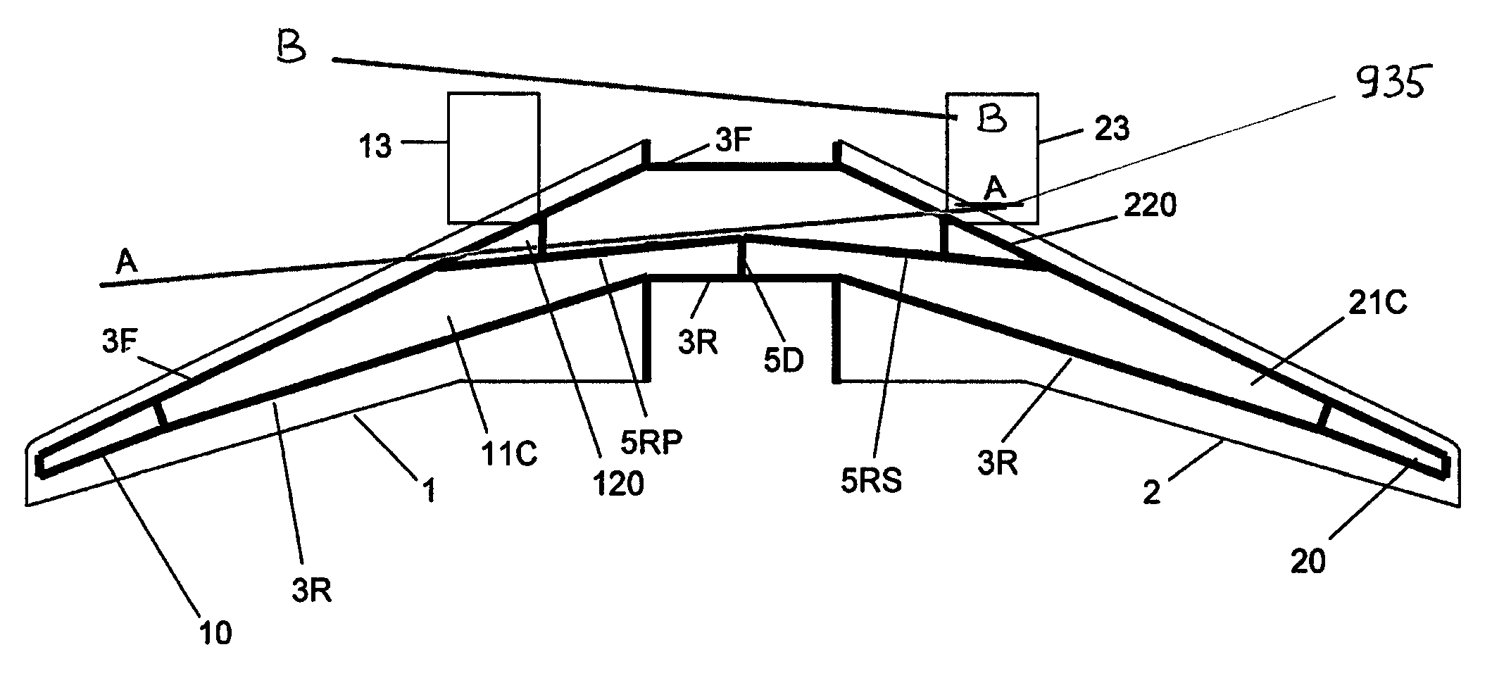
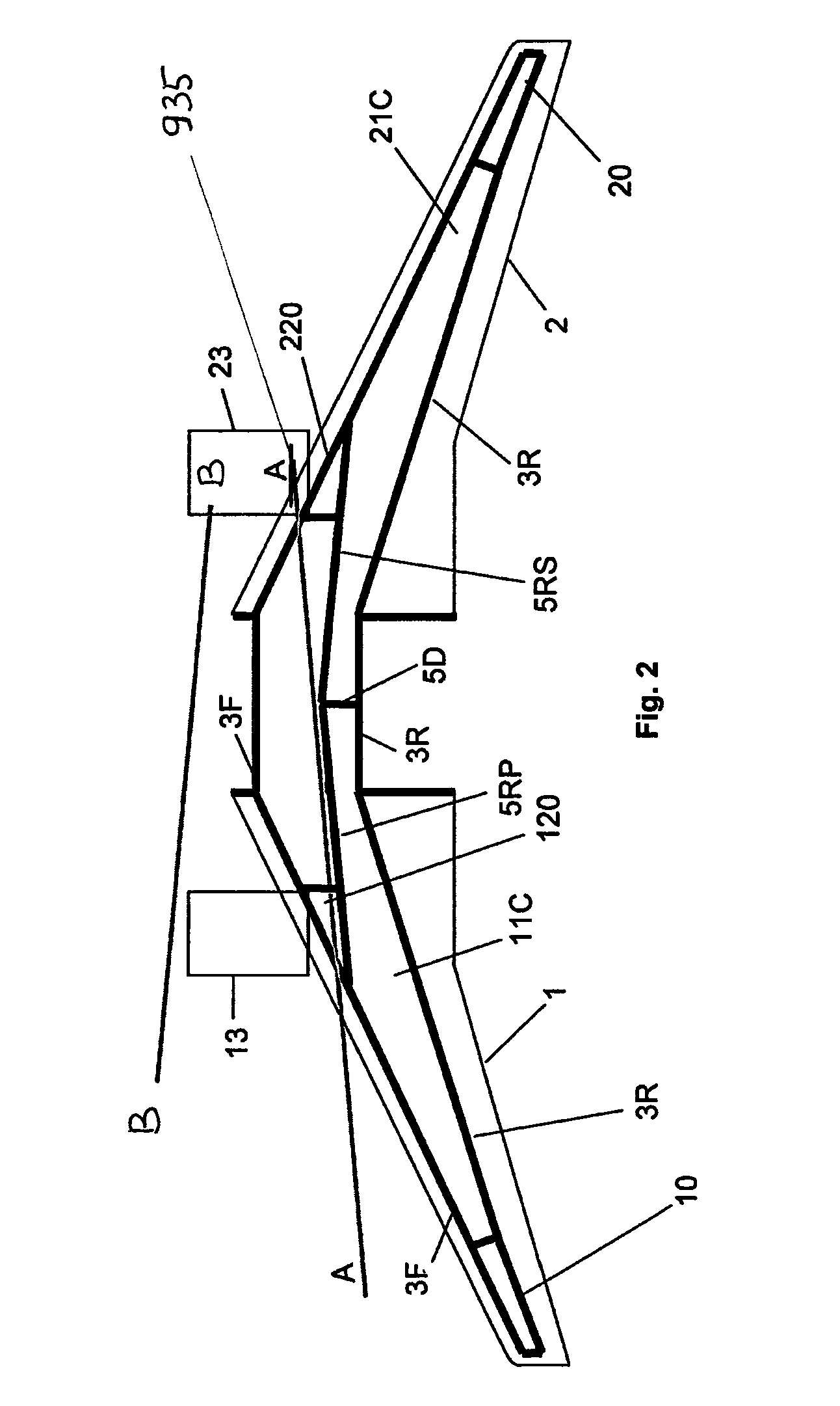
[0052]In the following description and in the accompanying drawings various reference numerals include the letters F, R, P, S & T; these letters are used generally to denote, respectively, front, rear, port, starboard and transverse.

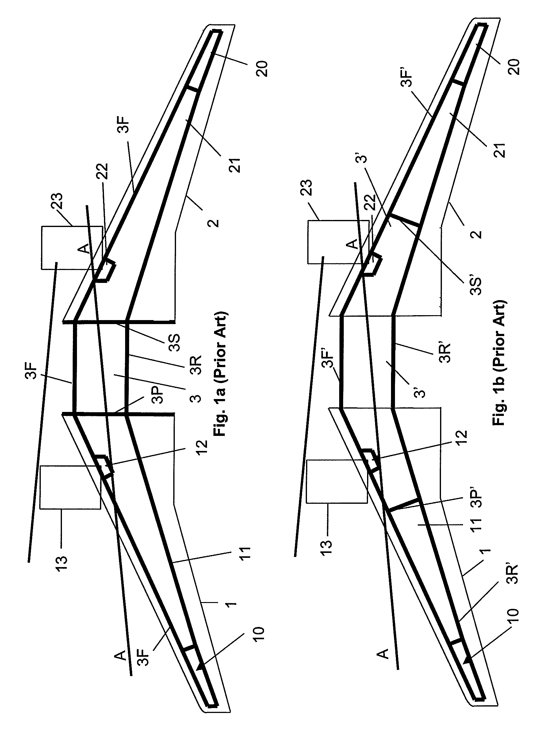
[0053]FIG. 1a shows a first configuration for fuel tanks in an aircraft wing assembly of the prior art. The assembly includes a central wing element, a port wing 1 and a starboard wing 2. Accommodated in the wing are various tanks including a central fuel tank 3, a port vent tank 10, a port inner tank 11, a starboard vent tank 20 and a starboard inner tank 21. The position occupied by a port engine is indicated as 13 and the position occupied by a starboard engine is indicated as 23. A port dry bay 12 occupies a position adjacent to the position 13 of the port engine and a starboard dry bay 22 occupies a position adjacent to the position 23 of the starboard engine.

[0054]The central fuel tank 3 is defined by a front boundary member 3F extending to the fro...


PUM


Abstract

On failure, a burst rotor of a wing-mounted engine (13, 23) can penetrate fuel tank walls in the wing of a conventional aircraft. There exists a zone that is at risk of such damage. Thus, the layout of fuel tanks (3, 11C, 21C) in the wing of an aircraft in accordance with embodiments includes port and starboard inner fuel tanks (11C, 21C) that are positioned adjacent to a central fuel tank (3) in the central wing section, but outside of the at-risk zone. Each of the port and starboard inner fuel tanks (11C, 21C) is defined in part by a respective inner boundary member (5RP, 5RS) that when viewed in plan extends, at least in part, in a direction at an angle of less than 20° to the adjacent vertical plane (A-A) defining the at-risk zone. Thus the amount of fuel stored in fuel tanks (11C, 21C) in the wing assembly that cover a region outside of the at-risk zone and that do not extend into the at-risk zone may be increased.

Description

RELATED APPLICATIONS[0001]The present application is based on, and claims priority from, British Application Number 0518576.4, filed Sep. 12, 2005, the disclosure of which is hereby incorporated by reference herein in its entirety.TECHNICAL FIELD[0002]The invention relates to an aircraft wing assembly including a port wing and a starboard wing which, in use, carries port and starboard engines and serves to accommodate a plurality of fuel tanks.BACKGROUND OF THE INVENTION[0003]Internal combustion gas turbines used in aircraft engines are known, albeit with low probability, to fail and on failing, to shower a region in the vicinity of the failed engine with high-speed debris which has the potential to penetrate the structure, including the fuel tanks, of the aircraft. A result of such engine failure could be the rapid loss of fuel from a fuel tank or tanks, in which case the aircraft may be unable to reach its intended destination as a result of fuel loss.SUMMARY OF THE INVENTION[0004...

Claims


Application Information

Patent Timeline
Patent Type & Authority Patents(United States)
IPC IPC(8): B64D37/04B64C3/34B64C17/10
CPCB64C3/34B64D37/04B64C17/10
Inventor WARD, MICHAEL DAVID
Owner AIRBUS OPERATIONS LTD
Why Eureka
Try Eureka