Electric connector assembly kit and shielded cable harness

a technology of shielding cable and assembly kit, which is applied in the direction of coupling device details, coupling device connection, coupling protective earth/shielding arrangement, etc., can solve the problems of low workability of production, solder cracking, and performance cannot be maintained, so as to enhance the connection strength and enhance the connection strength between the plug cover and the plug shell

Active Publication Date: 2009-10-13
JST MFG CO LTD
View PDF8 Cites 24 Cited by
  • Summary
  • Abstract
  • Description
  • Claims
  • Application Information

AI Technical Summary

Benefits of technology

[0006]The present invention was made in view of such points, and its object is to enhance as much as possible the connection strength between the electric connector and the shielded cable and the assemblage strength of the shell in the electric connector against the pulling-about forces of the shielded cable by, without relying on soldering, press-fitting a crimping part of a member corresponding to said basic shell into a U-shaped slot of a plug shell and also coupling a plug cover shell being opposite to the plug shell with a housing in between to the plug shell.
[0017]With this arrangement, the connection strength between the plug cover shell and the plug shell is enhanced further, and in turn the connection strength between the electric connector and the shielded cable and the assemblage strength of the shell in the electric connector against the pulling-about forces of the shielded cable are enhanced further.

Problems solved by technology

This, however, requires the soldering work and in turn lowers the workability of the production, and it also poses a problem that solder will undergo cracking due to repeated exposure to the pulling-about forces and the performance cannot be maintained over a long period.

Method used


Image

  • Electric connector assembly kit and shielded cable harness
  • Electric connector assembly kit and shielded cable harness
  • Electric connector assembly kit and shielded cable harness

Examples


Embodiment Construction

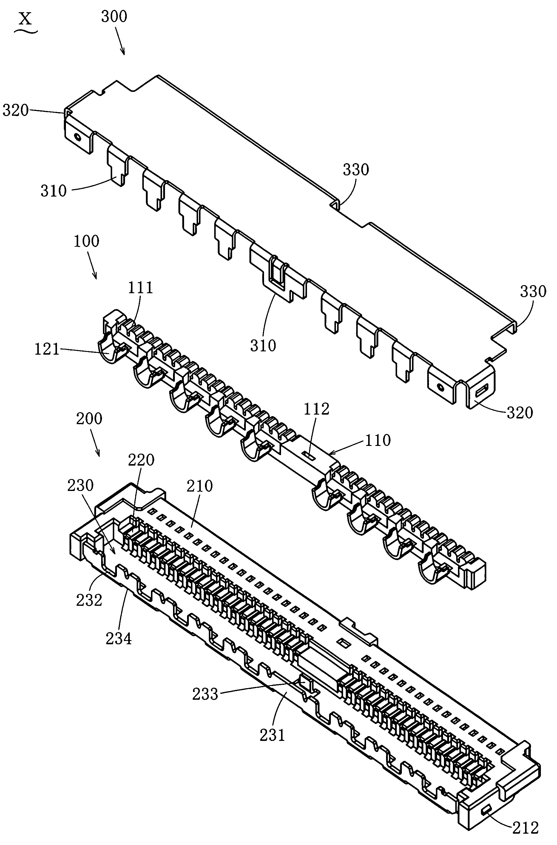
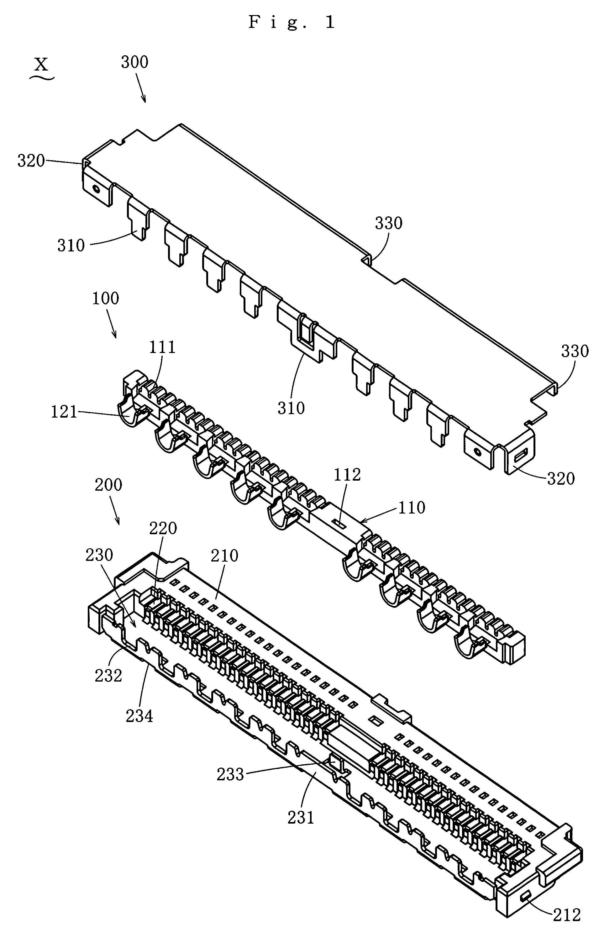
[0045]In the following, one embodiment according to the present invention will be described. FIG. 1 illustrates one embodiment of the electric connector assembly kit of the present invention. This electric connector assembly kit X is connected to ends of shielded cables 400 to form an electric connector Y. The shielded cables 400 and the electric connector Y being connected to the ends of the shielded cables 400 constitute a shielded cable harness Z.

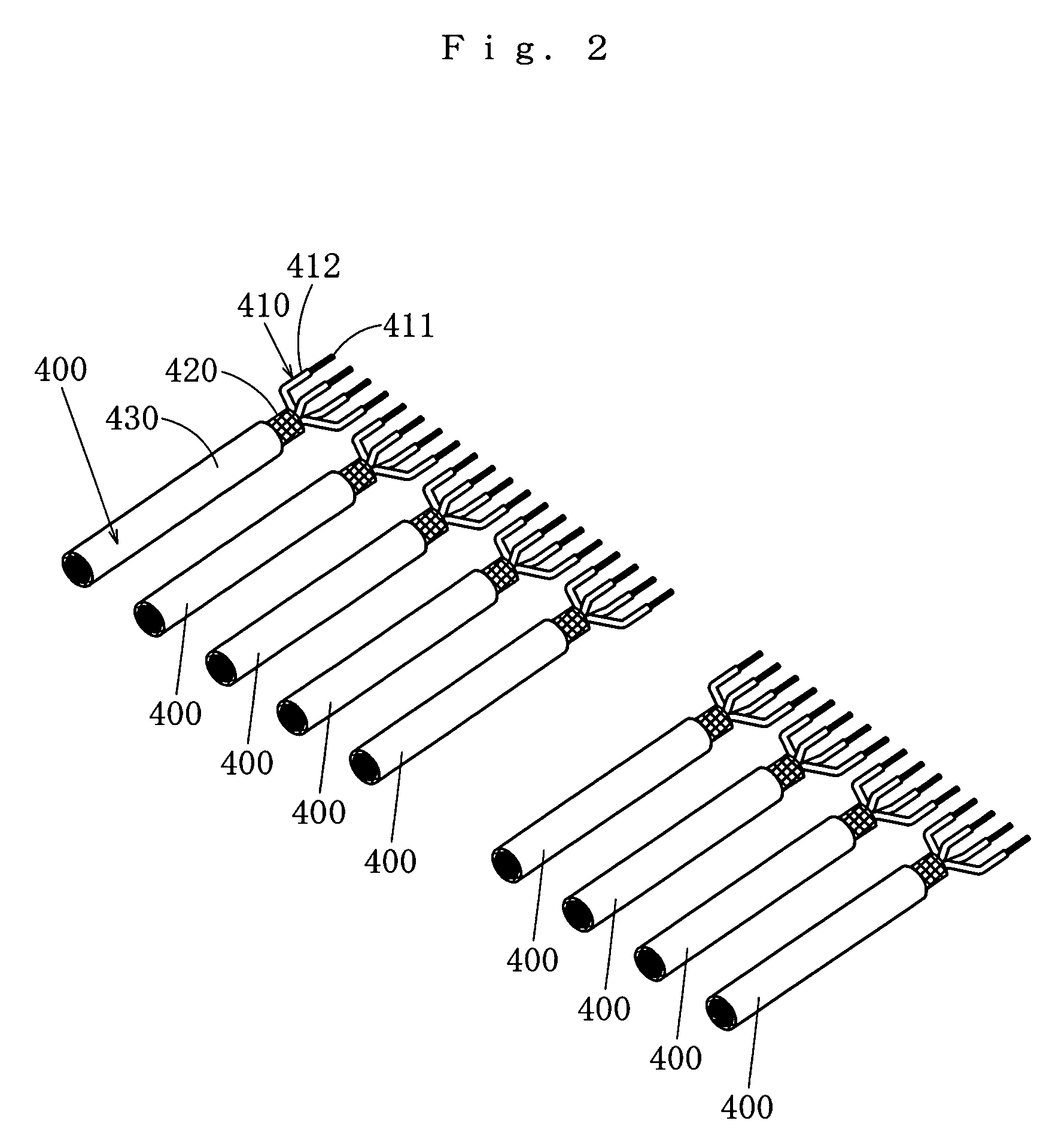
[0046]As shown in FIG. 27, the shield cable 400 comprises inner wires 410 being inner conductors 411 covered by inner insulating coatings 412, an outer conductor 420 covering the inner wires 410, and an outer insulating coating 430 covering the outer conductor 420. This shielded cable 400 is provided with an intermediate shielding coating between the inner wires 410 and the outer conductor 420 to separate them from each other. The inner insulating coatings 412, the outer insulating coating 430 and the intermediate insulating coating are ...


PUM


Abstract

The electric connector assembly kit is structured that the inner wire of the end of the shielded cable is fitted and held in the wire holding part of the wire holder and the outer conductor is crimped by the barrel, the connector body is set on the lower side of the wire holder, the inner conductor of the inner wire is connected to the contact and the barrel is press-fitted in the U-shaped slot, the plug cover shell is set on the higher side of the wire holder and made to contact the barrel, and the top end of the coupling piece extending toward the lower side between the U-shaped slots is bent toward the back side in the depth direction and hooked on the plug shell from the lower side to assemble onto the end of the shielded cable.

Description

BACKGROUND OF THE INVENTION[0001]1. Field of the Invention[0002]The present invention belongs to a technical field of electric connector and relates to an electric connector assembly kit to be assembled onto an end of a shielded cable, and a shielded cable harness comprising a shielded cable and an electric connector connected to an end of the shielded cable.[0003]2. Description of the Related Art[0004]Japanese Patent Publication (unexamined) No. 2006-294572 discloses an electric connector to be connected with a shielded cable comprising a signal line being a covered electric wire having a conductor and an insulating coating covering it, an outer conductor covering the signal line, and an outer insulating coating covering the outer conductor. The electric connector for this shielded cable comprises an insulating first housing having a line holding part for holding the exposed signal line, a conductive basic shell being fixed onto the first housing and having a crimping part to be cr...

Claims


Application Information

Patent Timeline
Patent Type & Authority Patents(United States)
IPC IPC(8): H01R13/648H01R13/646H01R13/658
CPCH01R4/20H01R9/0518H01R13/6593H01R24/50H01R13/582H01R2103/00
Inventor HORIUCHI, HIDEAKIMORIWAKE, RYO
Owner JST MFG CO LTD
Why Eureka
Try Eureka