System of stowing and deploying multiple phased arrays or combinations of arrays and reflectors

a technology of arrays and reflectors, applied in the field of spacecraft elements storage and deployment, can solve the problems of mass imbalance, increasing difficulty in support, deployment, steering, etc., and achieve the effect of efficient use of the available volum

Active Publication Date: 2009-10-13
LOCKHEED MARTIN CORP
View PDF9 Cites 14 Cited by
  • Summary
  • Abstract
  • Description
  • Claims
  • Application Information

AI Technical Summary

Benefits of technology

[0006]The present invention solves the foregoing problems by providing a stowage system that allows the packaging of one or more phased arrays and reflectors on the East and West sides of a spacecraft in order to distribute the mass of the spacecraft in a more symmetrical manner. This stowage system more efficiently uses the available volume in a launch vehicle and allows phased arrays and reflectors to have their own deployment, retention, and pointing systems, while requiring fewer common launch restraint systems.

Problems solved by technology

One of the problems of stowing and deploying both phased arrays and antenna reflectors on the same spacecraft is the mass imbalance created by stowing an array on one side and a reflector on the other.
On-orbit control of the spacecraft may also become troublesome.
Additional problems are encountered when multiple phased arrays or phased array assemblies are provided on a single spacecraft.
The mass and size of the spacecraft makes it increasingly difficult to support, deploy, and steer.
Moreover, in systems in which each phased array or phased array assembly is provided with its own launch restraint system or tie downs, the increased mass of the launch restraints and launch restraint severing systems will further impact the useful payload of the spacecraft.

Method used


Image

  • System of stowing and deploying multiple phased arrays or combinations of arrays and reflectors
  • System of stowing and deploying multiple phased arrays or combinations of arrays and reflectors
  • System of stowing and deploying multiple phased arrays or combinations of arrays and reflectors

Examples


Embodiment Construction

[0014]In the following detailed description, numerous specific details are set forth to provide a full understanding of the present invention. It will be apparent, however, to one ordinarily skilled in the art that the present invention may be practiced without some of these specific details. In other instances, well-known structures and techniques have not been shown in detail to avoid unnecessarily obscuring the present invention.

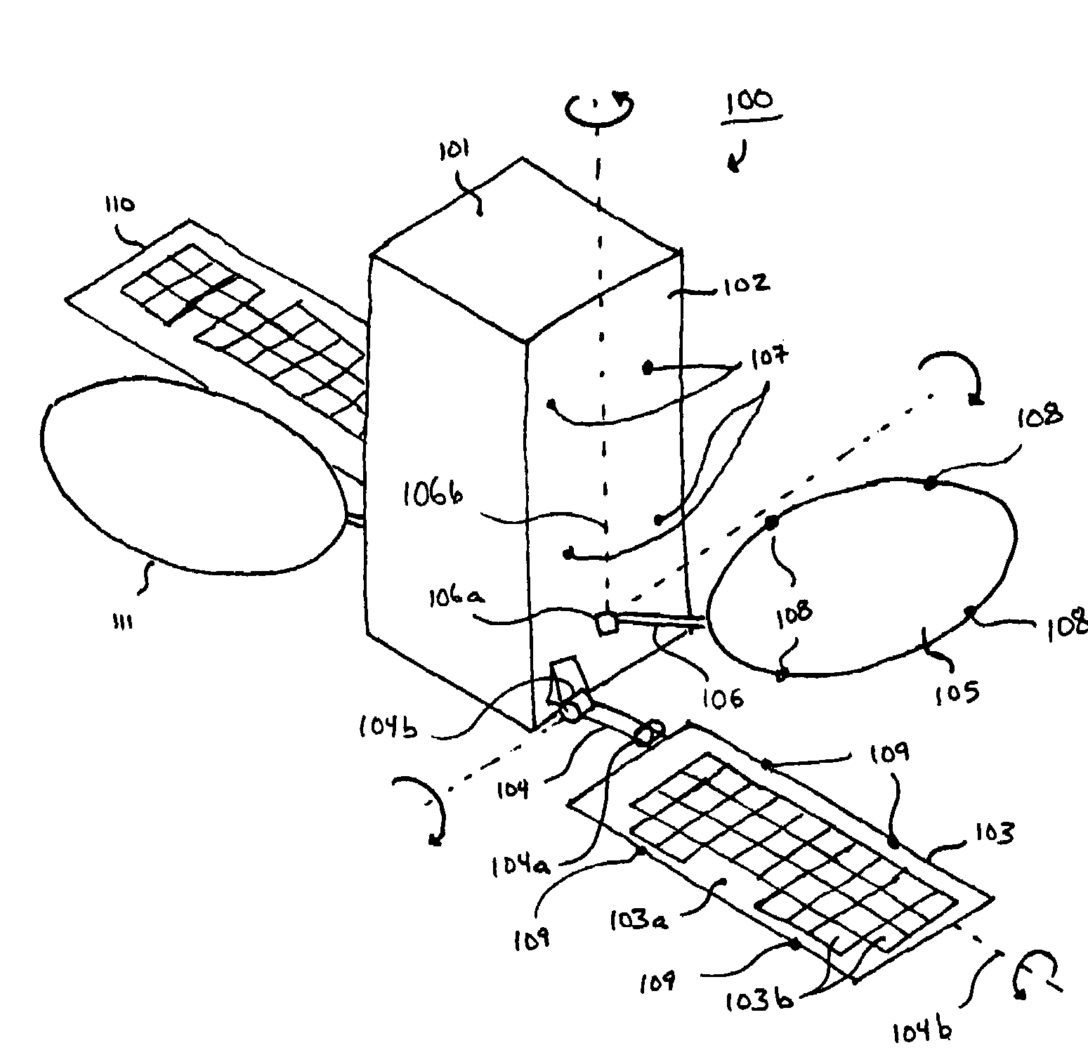
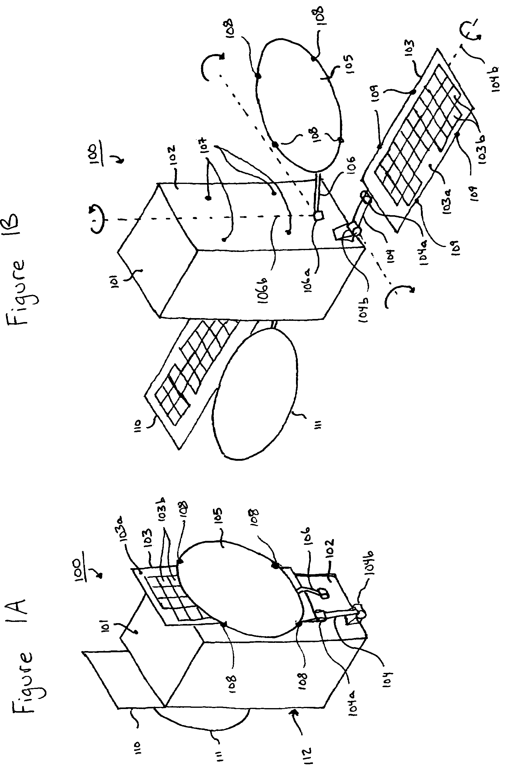
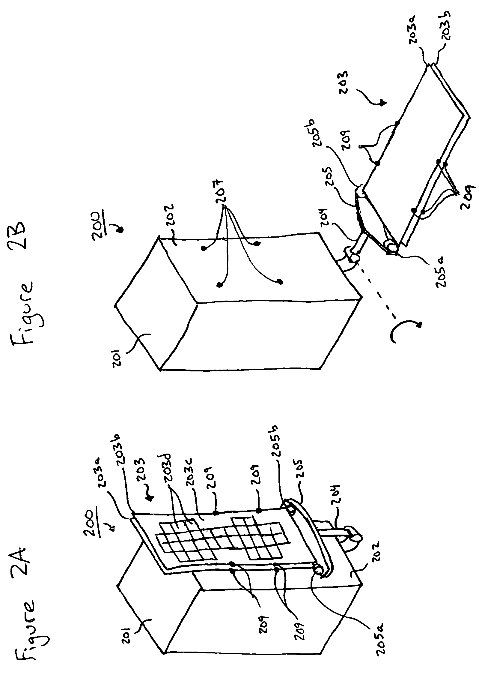
[0015]Deployable phased arrays and launch restraint subsystems are designed to increase the flexibility, configurability and capability of modem satellites. In this regard, the stowed state is a state in which launch restraints are restraining the phased arrays or phased array assemblies in place for transport, and the deployment couples are in a volume-minimizing, retracted position. The deployed state is a state in which the launch restraints have been removed, and the phased arrays or phased array assemblies have been moved from the stowed position and...


PUM


Abstract

A spacecraft is provided that includes a spacecraft body, a phased array coupled to a side of the spacecraft body by a first deployment couple, and a reflector coupled to the side of the spacecraft body by a second deployment couple. The first and second deployment couples are configured to permit stowing the reflector and the phased array parallel to the side of the spacecraft body. The reflector and the phased array share a common launch restraint mounting point on the side of the spacecraft body. A spacecraft is also provided that includes a spacecraft body, a mounting platform coupled to a side of the spacecraft body by a deployment couple, and a plurality of phased array assemblies. Each phased array assembly has a face with elements, and is coupled to the mounting platform by a gimbal. The deployment couple and the gimbals are configured to permit stowing the phased array assemblies parallel to the side of the spacecraft body and with the face of each phased array assembly oriented in a first direction. The phased array assemblies share a common launch restraint mounting point on the side of the spacecraft body.

Description

CROSS-REFERENCE TO RELATED APPLICATION[0001]The present application claims the benefit of priority under 35 U.S.C. §119 from U.S. Provisional Patent Application Ser. No. 60 / 776,200 entitled “SYSTEM OF STOWING AND DEPLOYING MULTIPLE PHASED ARRAYS OR COMBINATIONS OF ARRAYS AND REFLECTORS,” filed on Feb. 24, 2006, the disclosure of which is hereby incorporated by reference in its entirety for all purposes.STATEMENT REGARDING FEDERALLY SPONSORED RESEARCH OR DEVELOPMENT[0002]Not applicable.FIELD OF THE INVENTION[0003]The present invention generally relates to the stowage and deployment of spacecraft elements and, in particular, relates to the stowage and deployment of multiple phased arrays or combinations of phased arrays and reflectors.BACKGROUND OF THE INVENTION[0004]One of the problems of stowing and deploying both phased arrays and antenna reflectors on the same spacecraft is the mass imbalance created by stowing an array on one side and a reflector on the other. If one side of a sp...

Claims


Application Information

Patent Timeline
Patent Type & Authority Patents(United States)
IPC IPC(8): H01Q3/02
CPCH01Q1/1228H01Q1/288H01Q21/062H01Q19/12H01Q3/08Y10S343/02
Inventor HENTOSH, DAVID J.EDRIDGE, MICHAEL J.
Owner LOCKHEED MARTIN CORP
Why Eureka
Try Eureka