
Head-up display system

a display system and head-up display technology, applied in the field of head-up display, can solve the problems of difficult to correct standard designs, difficult to correct tilt power combiners inherently, and difficult to correct pupil-imaging hud designs, etc., to achieve the effect of reducing development costs and non-recurring expenses

Active Publication Date: 2009-10-13
ELBIT SYST ELECTRO OPTICS ELOP
View PDF4 Cites 83 Cited by
  • Summary
  • Abstract
  • Description
  • Claims
  • Application Information

AI Technical Summary

Benefits of technology

[0009]An object of the present invention is to provide a head-up display system which does not require holographic elements, and which can be implemented by the use of a few relatively simple optical elements. Another object of the invention is to provide a head-up display system which is of a flexible design and which inherently permits the system to be tailored for different applications with a minimum of development costs and non-recurring expenses.
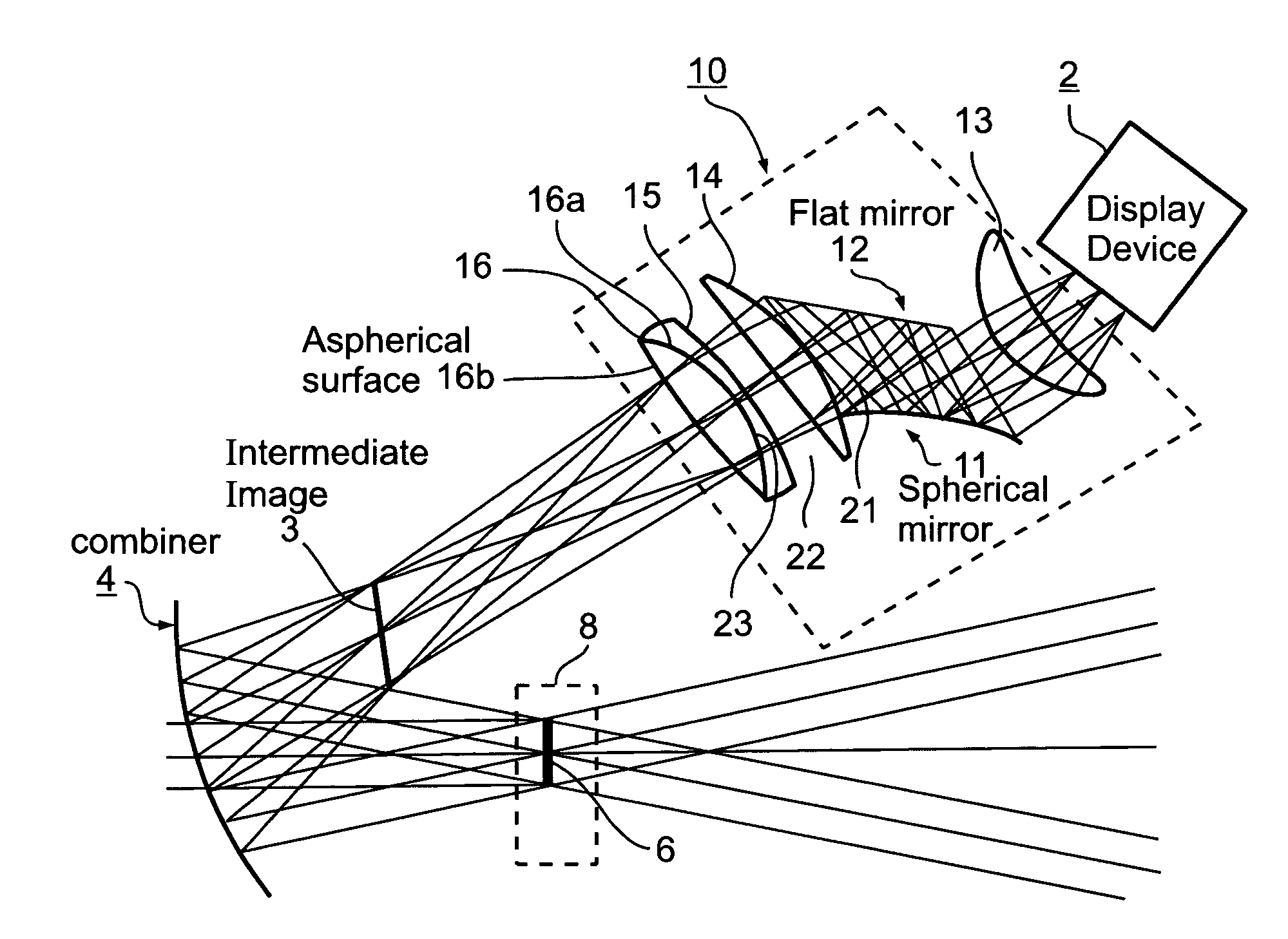
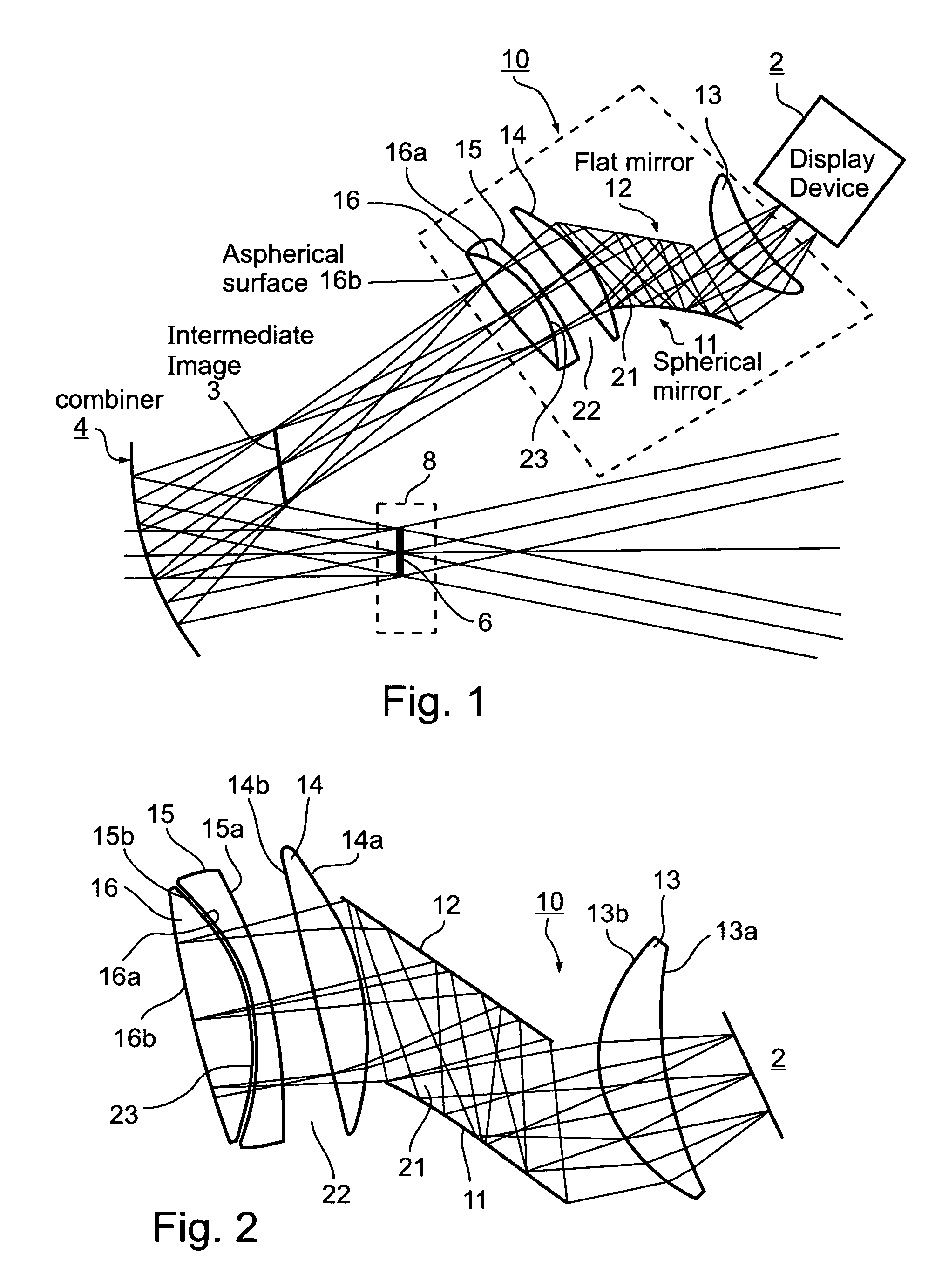
[0011]According to further features in the described preferred embodiment, the relay optic assembly further includes a flat mirror spaced from a spherical mirror such as to receive reflections directly therefrom. In the described preferred embodiment, the flat mirror is spaced from the spherical mirror by an air gap, and the position of the flat mirror relatively to the spherical mirror is variable. Such an arrangement imparts flexibility to the design, enabling the system to be tailored for different applications with a minimum of initial development costs and non-recurring expenses.
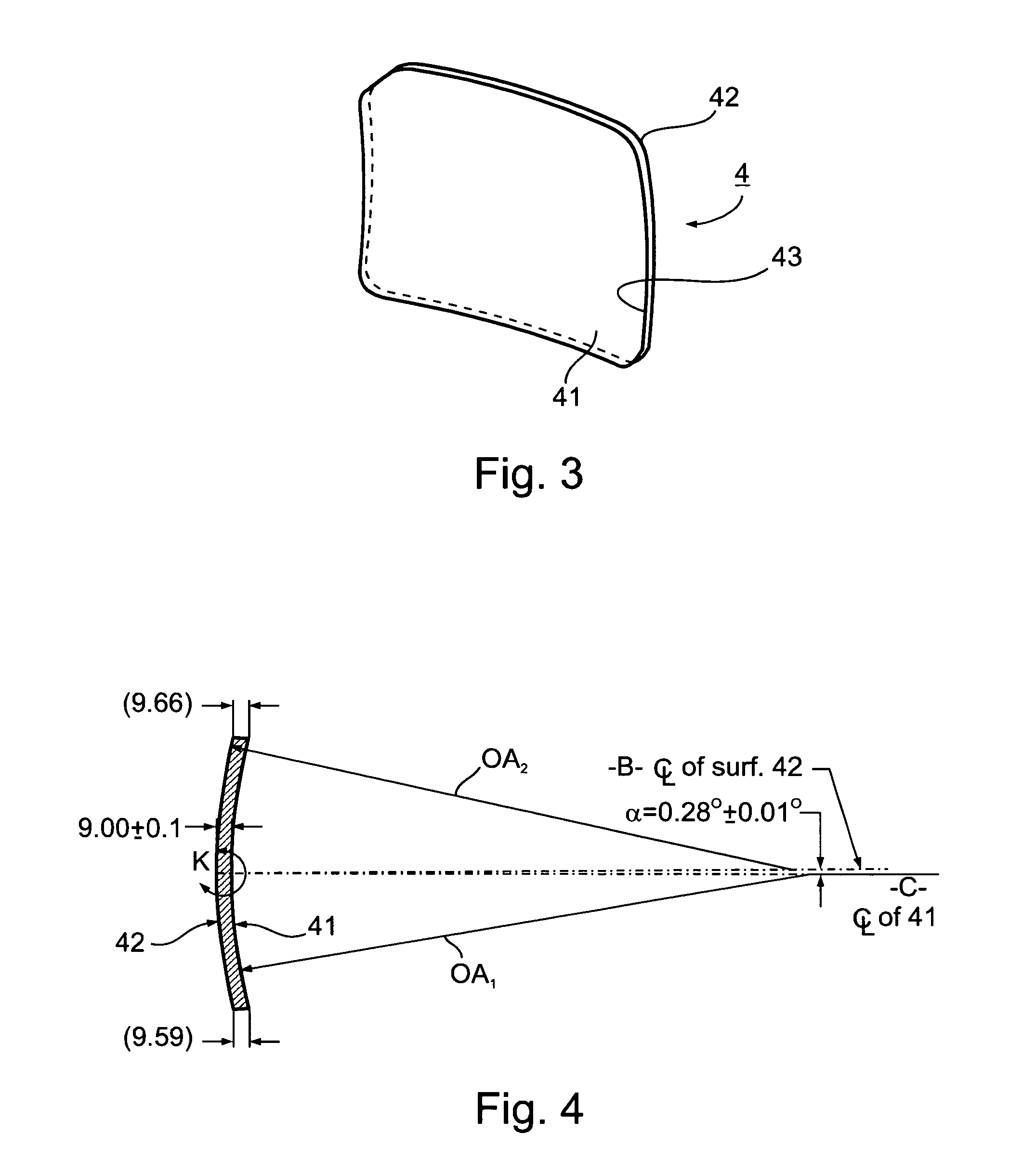
[0012]According to another aspect of the present invention, there is provided a head-up display system, comprising: a display device for generating and displaying information to an eye of an observer; a tilted power combiner for superimposing the information displayed by the display device into the forward view of the outside by the eye of the observer; and a relay optic assembly between the display device and the tilted power combiner for forming an intermediate image of the displayed information forwardly of the combiner that reflects the image towards the eye of the observer within an eye motion box to produce a large field of view for the observer; the tilted power combiner including a front surface of a first curvature having a first optical axis, and a back surface of a second curvature having a second optical axis at a predetermined angle to the first optical axis, such that the tilted power combiner is of a wedge configuration with the predetermined angle defining the wedge angle of the combiner.
[0013]A combiner constructed as described above thus has an inherent built-in wedge which serves to correct line-of-sight errors. Such a construction also eliminates the need for a doublet for the combiner which, as indicated above, was heretofore generally used to correct for both parallax errors and line-of-sight errors due to the radius or power of the combiner. Many of the other drawbacks mentioned above, such as the need for relatively complex, costly, and heavier elements particularly in the conventional holographic HUD systems, may thus be reduced or eliminated in systems constructed according to the present invention.
[0014]According to a further aspect of the present invention, there is a provided a head-up display system comprising a display device for generating and displaying information to an observer; a tilted power combiner for superimposing the information displayed by the display device into the forward view of the outside by the observer; and a relay optic assembly between the display device and the tilted power combiner for forming an intermediate image of the displayed information forwardly of the combiner that reflects the image towards the eye of the observer within an eye motion box forwardly of the combiner to produce a large field of view for the observer; the tilted power combiner having a front surface, a back surface, and a dichroic coating on the front surface.
[0015]Such a system thus achieves the optimal reflection and transmission characteristics, not by the use of holographic elements as in the previous systems, but rather by the use of a narrow band thin-film dichroic coating on the combiner. This is advantageous not only because such a coating can be applied with relative ease and at low cost, but also because the use of thin film coatings produces a more natural representation of the outside world with negligible color shift.

Problems solved by technology

Tilted power combiners inherently produce aberrations which are difficult to correct in the relay optic assembly.
Moreover, many of the known pupil-imaging HUD designs lack the ability to view the total field of view over the entire exit pupil because of inherent design limitations.
This is mainly due to the aberrations typically seen at the edges of the eye motion box, which are also difficult to correct using standard designs.
Such doublets, besides being relatively complex and therefore costly to produce, are relatively heavy and therefore more sensitive to line-of-sight movements resulting from platform vibrations.
It is thus seen that the design of the relay optic assembly in a pupil-imaging HUD is difficult and complicated for achieving high-quality imagery over a reasonable field of view.
However, relay optic assemblies based on holography involve not only high initial development costs, but also high non-recurring expenses since each system generally must be specially designed for each particular application.

Method used


Image

  • Head-up display system
  • Head-up display system
  • Head-up display system

Examples


Embodiment Construction

[0023]The head-up display system illustrated in FIG. 1 includes a display device 2 for generating and displaying information to an observer, and a tilted power combiner 4 for superimposing the information displayed by the display device into the forward view of the outside world by the observer. Display device 2 may be a CRT, an LCD, or a similar device for generating and displaying information, such as aircraft information normally displayed on an instrument panel.

[0024]In order to provide a large instantaneous field of view to the observer, the information displayed by display device 2 is formed into an intermediate image in a plane 3 forwardly of the combiner 4 and reflected towards the eye of the observer. Plane 6 defines the location of the observer's eye-pupil according to the design eye position (DEP) of the respective head-up display system. Such systems are generally designed so that the DEP plane fits within a prescribed eye motion box, generally designated 8. The eye moti...


PUM


Abstract

A head-up display system includes a display device for generating and displaying information to an eye of an observer; a tilted power combiner for superimposing the information displayed by the display device onto the forward view of the outside by the eye of the observer; and a relay optic assembly between the display device and the tilted power combiner for forming an intermediate image of the displayed information forwardly of the combiner that reflects the image towards the eye of the observer within an eye motion box to produce a large field of view for the observer. The relay optic assembly is void of holographic elements and includes a spherical mirror generating aberrations in the intermediate image tending to compensate for aberrations produced by the tilted power combiner.

Description

RELATED APPLICATION[0001]This application includes subject matter, and claims the priority date of Israel Patent Application No. 168581, filed on May 15, 2005, the contents of which are incorporated herein by reference.FIELD AND BACKGROUND OF THE INVENTION[0002]The present invention relates to head-up display (or HUD) systems for displaying information to an observer in a manner conveniently seen by the observer.[0003]Head-up display systems have been used for many years, particularly in military aircraft but more recently in many other applications requiring the display of information to an observer in a manner conveniently seen by the observer. Such systems generally include a display device, such as a CRT or LCD, for generating and displaying information to the observer, and a tilted power combiner for superimposing the information displayed by the display device into the forward view of the outside world by the observer. The information to be displayed, e.g., instrument panel in...

Claims


Application Information

Patent Timeline
IPC IPC(8): G02B27/14
CPCG02B27/0103G02B2027/011G02B2027/0154G02B2027/0129G02B2027/0123
Inventor BLUMENFELD, YOEL
Owner ELBIT SYST ELECTRO OPTICS ELOP
Learn More