Sensor abnormality detecting method and electronic throttle control apparatus

a technology of electronic throttle control and abnormality detection, which is applied in the direction of electrical control, process and machine control, instruments, etc., can solve the problems of careless increase in the number of revolutions the inability to perform abnormality detection, and the affect of the operation state of the internal combustion engine to deteriorate the driving comfort, so as to prevent a careless increase in the number of revolutions and secure the traveling safety of the vehicl

Inactive Publication Date: 2009-10-20
MITSUBISHI ELECTRIC CORP
View PDF13 Cites 16 Cited by
  • Summary
  • Abstract
  • Description
  • Claims
  • Application Information

AI Technical Summary

Benefits of technology

[0015]It is another object of the invention to provide an electronic throttle control apparatus that can surely perform abnormality detection for an abnormality such as repeated fluctuation in a sensor output signal at the time of a sensor abnormality due to contact failure or the like of a throttle position sensor and can prevent a careless increase in the number of revolution of an internal combustion engine and an engine trouble and secure traveling safety of a vehicle.
[0017]Therefore, according to the sensor abnormality detecting method of the invention, it is possible to surely perform abnormality detection for an abnormality such as repeated fluctuation in a sensor output signal at the time of sensor abnormality.
[0019]According to the electronic throttle control apparatus of the invention, it is possible to surely perform abnormality detection for an abnormality such as repeated fluctuation in a sensor output signal at the time of a sensor abnormality due to contact failure of the throttle position sensor. Thus, it is possible to prevent a careless increase in the number of revolutions of an internal combustion engine and an engine trouble and secure traveling safety of a vehicle.
[0021]Therefore, according to the electronic throttle control apparatus of the invention, it is possible to surely perform abnormality detection for the first throttle position sensor. Since the target throttle opening value is limited according to the predetermined value at the time of abnormality detection and throttle opening control is performed on the basis of an output value of the normal second throttle position sensor, it is possible to prevent a careless increase in the number of revolutions of the internal combustion engine and an engine trouble and secure traveling safety of the vehicle.

Problems solved by technology

Therefore, in an abnormal state in which sensor output signals fluctuate repeatedly because of contact failure or the like of the sensors, abnormality detection cannot be performed when the fluctuation in the sensor output signals is shorter than the first predetermined time.
When the fluctuation is longer than the first predetermined time and shorter than the second predetermined time, since the stop of energization to the electric motor and the resumption of energization are performed repeatedly, an operation state of the internal combustion engine is affected to deteriorate drivability.
In the worst case, for example, a careless increase in the number of revolution of the internal combustion engine and an engine trouble occur.
Moreover, when the two sensors use a power supply and a ground in common, it is difficult to perform abnormality detection of the sensors concerning abnormalities such as fluctuation in two sensor output signals in the same phase due to contact failure in a power supply terminal and a ground terminal serving as common terminals and repeated fluctuation in a sensor output value due to contact failure of the sensors.
Thus, a detection ability for a sensor abnormality falls.

Method used


Image

  • Sensor abnormality detecting method and electronic throttle control apparatus
  • Sensor abnormality detecting method and electronic throttle control apparatus
  • Sensor abnormality detecting method and electronic throttle control apparatus

Examples


first embodiment

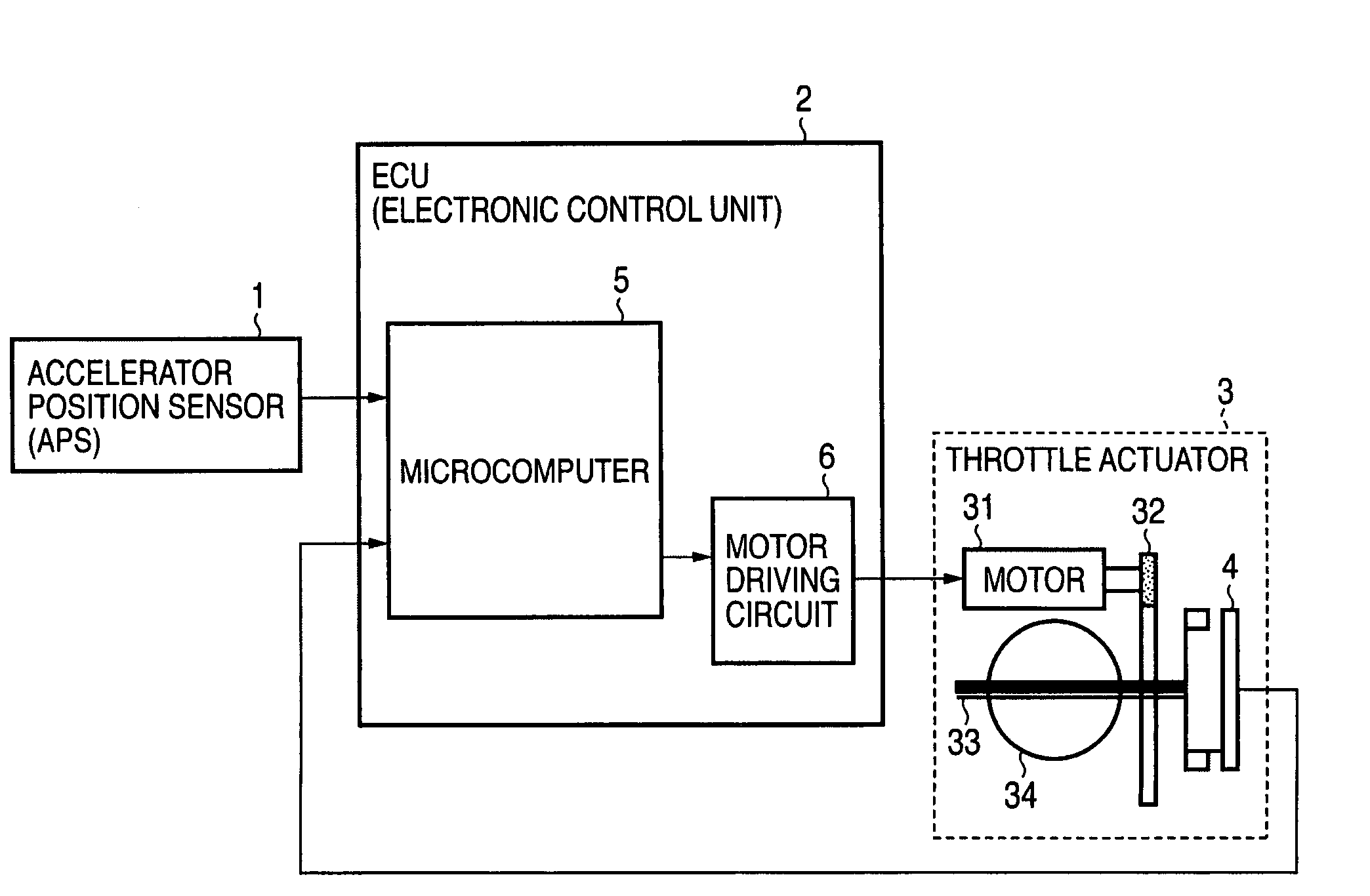
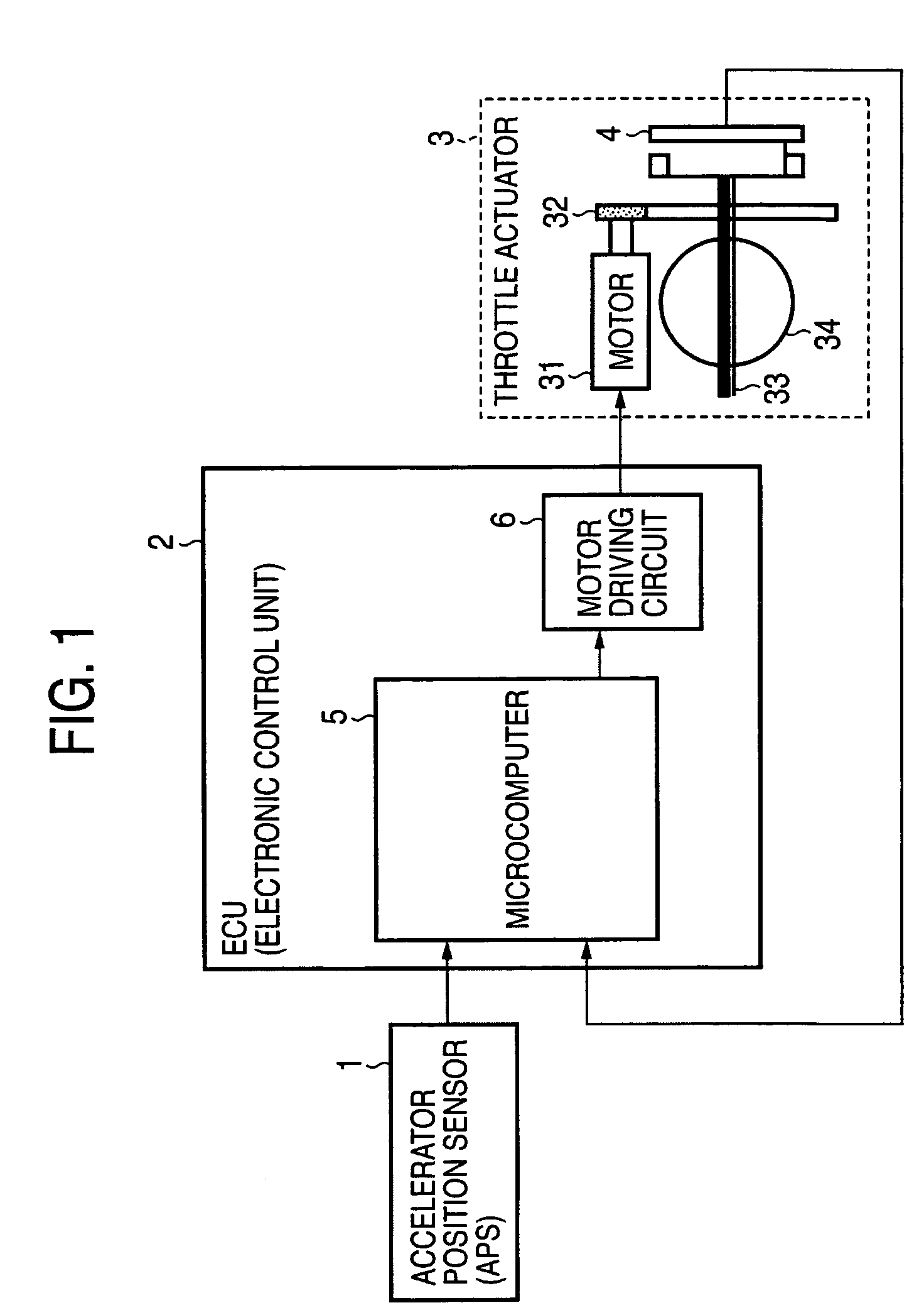
[0038]FIG. 1 is a diagram showing a schematic constitution of an electronic throttle control apparatus according to a first embodiment of the invention.

[0039]In FIG. 1, reference numeral 1 denotes an accelerator position sensor (APS) that detects a position of a not-shown accelerator pedal as an accelerator opening and 2 denotes an electronic control unit (ECU) that performs various kinds of internal combustion engine control. The ECU 2 includes a throttle control unit that performs supply air amount control for a not-shown internal combustion engine. The ECU 2 includes at least a microcomputer 5 and a motor driving circuit 6.

[0040]Reference numeral 3 denotes a throttle actuator. In the throttle actuator 3, a driving force of a motor 31 is transmitted to a throttle shaft 33 via a deceleration gear 32 in a decelerator to drive a throttle valve 34.

[0041]Reference numeral 4 denotes a throttle position sensor (TPS) of a potentiometer type that detects a throttle valve position as a thro...

second embodiment

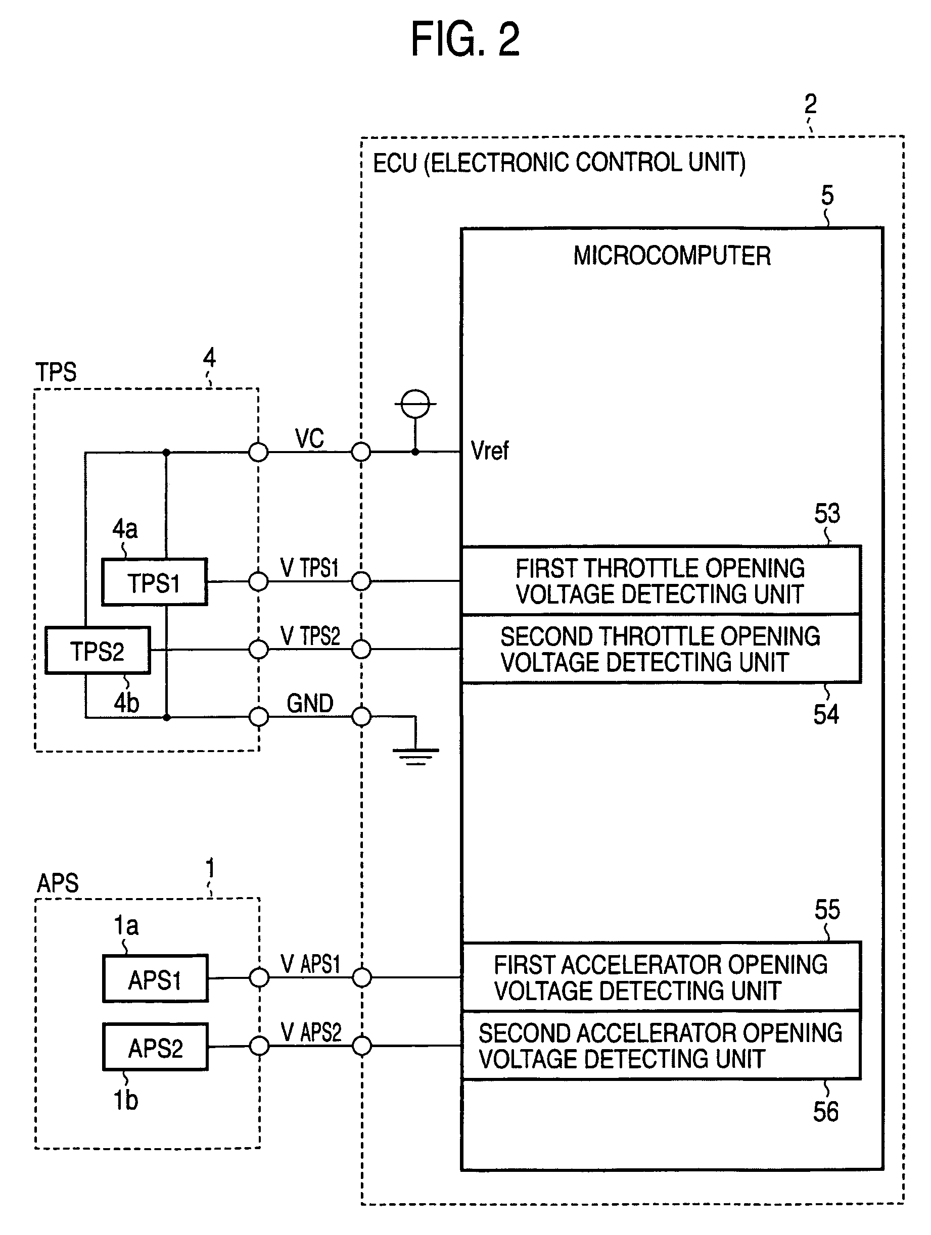
[0106]FIG. 11 shows a flow of TPS characteristic abnormality detection processing for a throttle position sensor in an electronic throttle control apparatus according to a second embodiment of the invention. Specifically, FIG. 11 shows a flow of TPS characteristic abnormality detection processing for the throttle position sensor 4 with the TPS output characteristic B (FIG. 5). As the output characteristic B, both the power supply terminal and the GND terminal of the throttle position sensor 4 output a voltage value proportional to a throttle opening as the output voltage VTPS1 of the first throttle position sensor (TPS1) 4a and output a voltage value inversely proportional to a throttle opening as the output voltage VTPS2 of the second throttle position sensor (TPS2) 4b.

[0107]First, the electronic throttle control apparatus judges whether the change (|VTAG(n)−VTAG(n−1)|) of the target throttle opening value VTAG is equal to or smaller than the predetermined value VR as a condition ...

third embodiment

[0117]FIG. 12 is a flowchart showing a flow of APS characteristic abnormality detection processing for an accelerator position sensor (APS) in an electronic throttle control apparatus according to a third embodiment of the invention.

[0118]First, the electronic throttle control apparatus judges whether a not-shown ignition switch (IG switch) is ON as a condition for carrying out the APS characteristic abnormality detection processing (step S100).

[0119]“n” indicates present sampling timing in a sampling period of an accelerator opening signal.

[0120]When the IG switch is OFF, the APS characteristic abnormality detection condition is not satisfied. Thus, the electronic throttle control apparatus initializes a timer counter value measuring time for calculating a sum of a change in a deviation of both APS output voltages of the first accelerator opening value VAPS1 and the second accelerator opening value VAPS2 (CNT4=CNTREF), clears a sum of a change in a deviation of both the APS output ...


PUM


Abstract

An electronic throttle control apparatus includes first and second throttle position sensors that detect an opening of a throttle valve for adjusting an amount of supply air to an internal combustion engine, a throttle control unit that controls to drive the throttle valve, first and second accelerator position sensors that detect an operation amount of an accelerator pedal, and an ECU that calculates control parameters for the internal combustion engine on the basis of internal combustion engine operation information including an accelerator opening and a throttle opening and controls a throttle actuator such that a throttle opening position coincides with a target throttle opening position included in the control parameters. The ECU surely detects an abnormality in a sensor output due to contact failure or the like of the throttle position sensors and the accelerator position sensors. As a result, it is possible to provide an electronic throttle control apparatus that can prevent an unintended increase in the number of revolutions of the internal combustion engine, an engine trouble, and the like.

Description

BACKGROUND OF THE INVENTION[0001]1. Field of the Invention[0002]The present invention relates to a sensor abnormality detecting method of detecting an abnormality in fluctuation in a sensor output signal due to contact failure of a sensor for detecting a control amount of a control object. In particular, the invention relates to an electronic throttle control apparatus including a sensor abnormality detecting unit that detects an abnormality of a throttle position sensor for detecting an opening amount of a throttle valve set in an intake pipe of an internal combustion engine for an automobile using the sensor abnormality detecting method.[0003]2. Description of the Related Art[0004]In an electronic control throttle system mounted on a vehicle, an opening of a throttle valve is detected by a throttle position sensor and a target opening of the throttle valve is set on the basis of an accelerator opening and an operation state of an internal combustion engine. The electronic control ...

Claims


Application Information

Patent Timeline
Patent Type & Authority Patents(United States)
IPC IPC(8): F02D11/10G06F19/00F02D9/02F02D41/22F02D45/00
CPCF02D9/02F02D11/107F02D2400/08F02D2200/602F02D2200/0404
Inventor WATANABE, SHINJI
Owner MITSUBISHI ELECTRIC CORP
Why Eureka
Try Eureka