Drive mechanism for an extendable member

a technology of extending member and drive mechanism, which is applied in the direction of transportation, transportation items, transportation and packaging, etc., to achieve the effect of preventing disengagemen

Inactive Publication Date: 2009-10-27
ELEVATOR
View PDF17 Cites 42 Cited by
  • Summary
  • Abstract
  • Description
  • Claims
  • Application Information

AI Technical Summary

Benefits of technology

[0005]Another object of the invention is to provide a drive mechanism for a recreational vehicle slide-out room that will prevent disengagement of the gear from the rack during operation of the drive mechanism while allowing vertical movement of the rack and gear.

Problems solved by technology

This has been particularly challenging when a rack and pinion mechanism is used to actuate a slide-out room since gear teeth used to engage a rack attached to a slide-out room tend to become disengaged as height of the slide-out room changes.

Method used


Image

  • Drive mechanism for an extendable member
  • Drive mechanism for an extendable member
  • Drive mechanism for an extendable member

Examples


Embodiment Construction

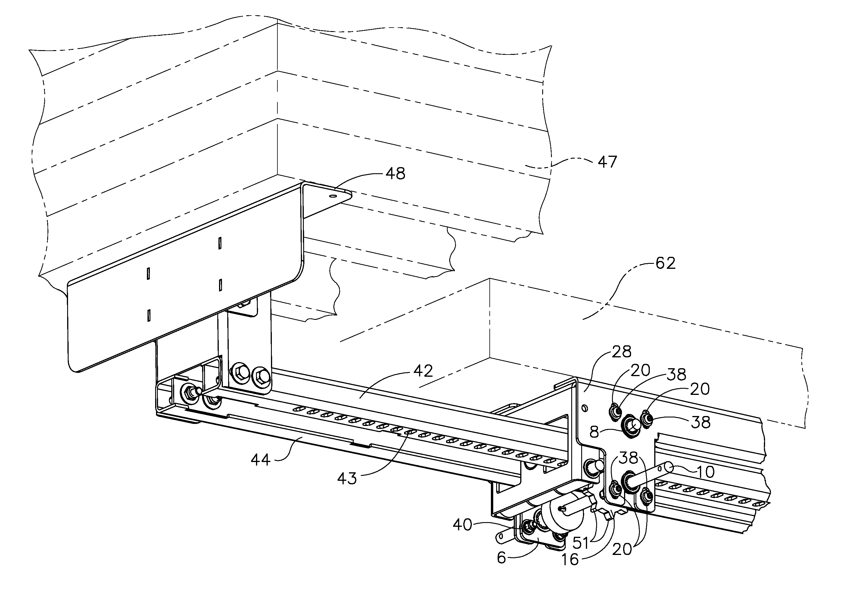
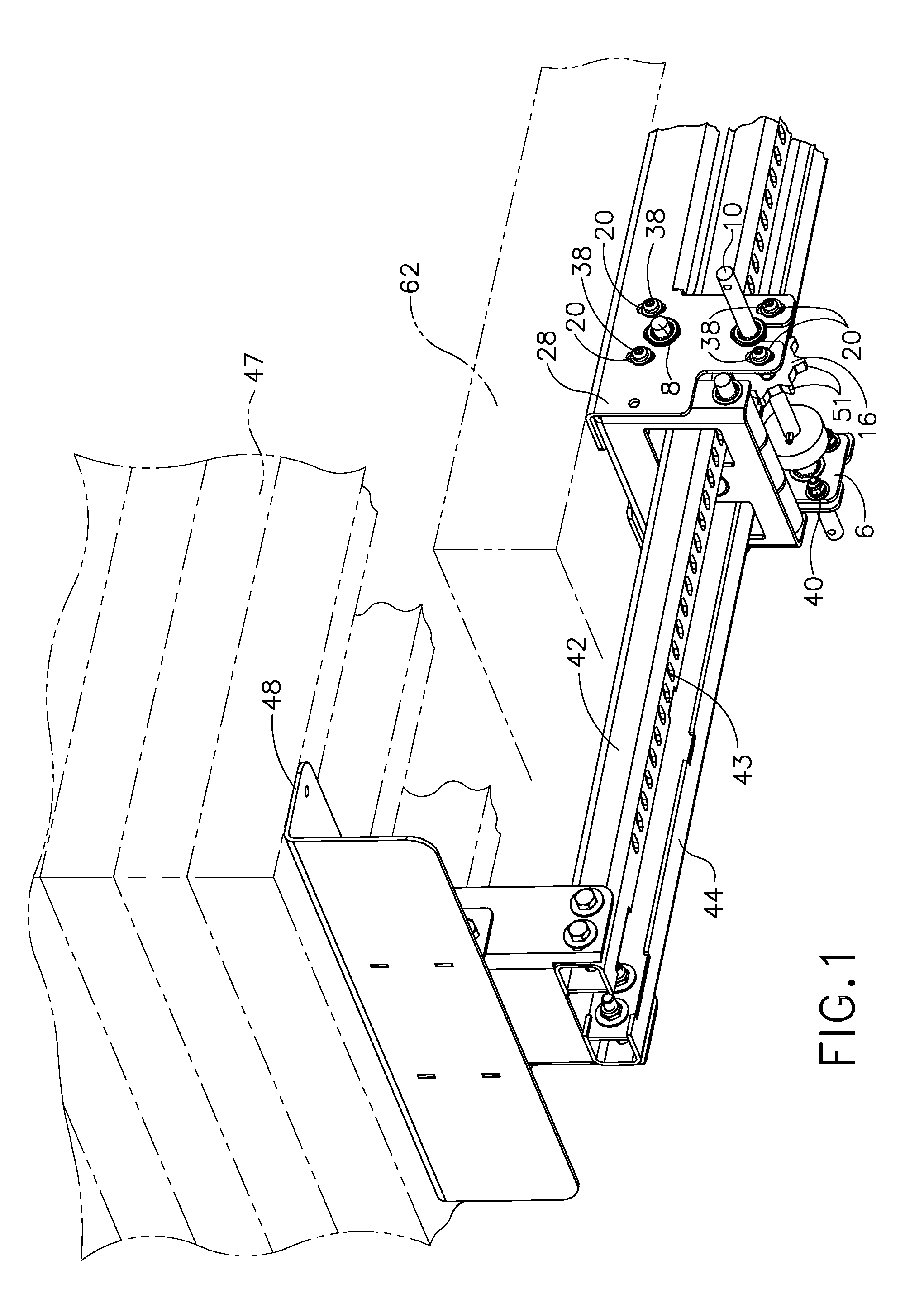
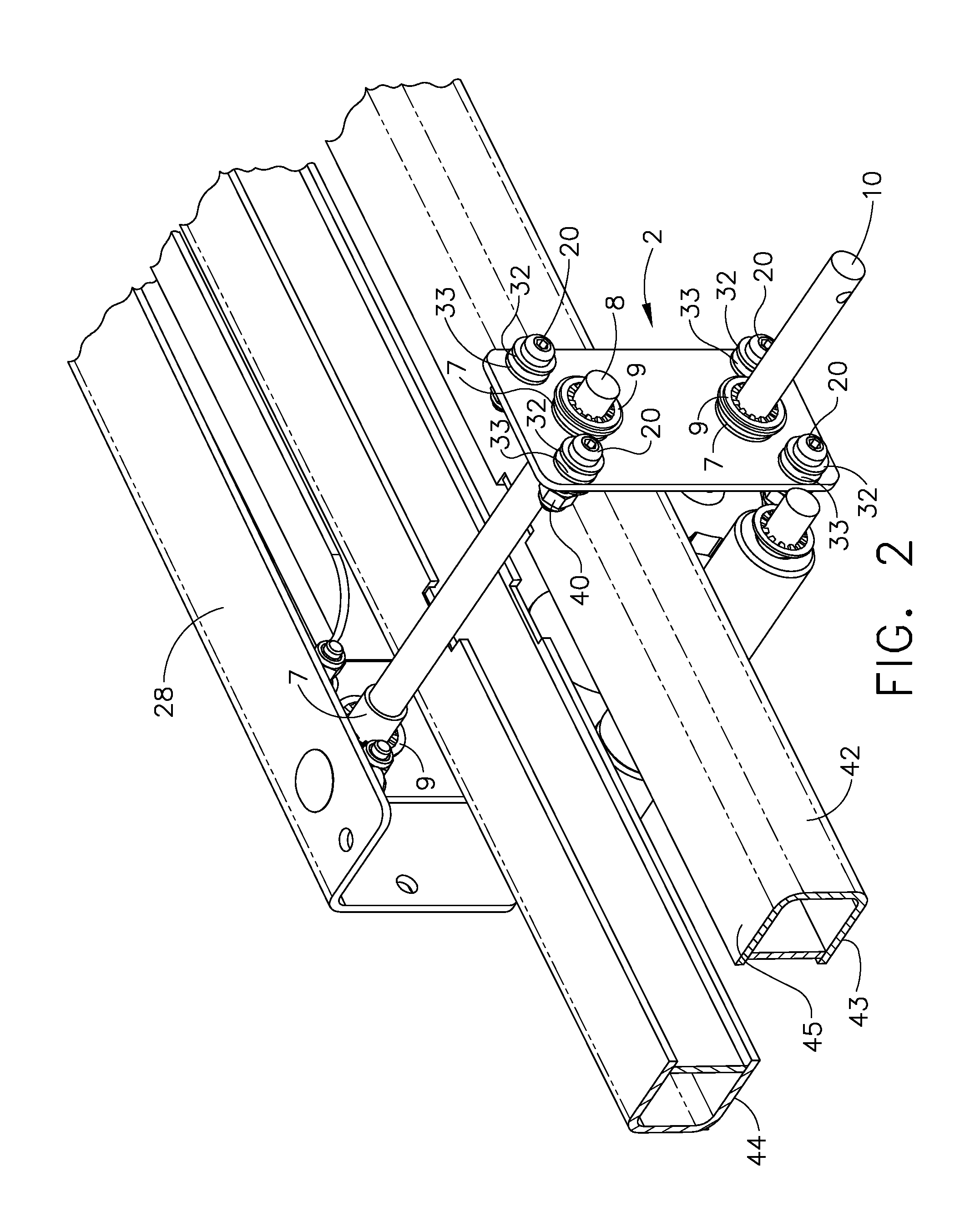
[0011]The drive mechanism 1 of this invention includes an engagement block 2 having a first side plate 4 and a second side plate 6 which are parallel and opposite each other. An engagement shaft 8 extends through holes 12 in the first and second side plates 4, 6 and is supported for rotation by bushings 7. A gear shaft 10 extends through holes 14 in the first and second side plates 4, 6 and is supported for rotation by bushings 7. The gear shaft 10 has a pinion or gear 16 mounted to the gear shaft 10 so that it rotates with the gear shaft 10. A support roller 18 is also attached to the gear shaft 10 and rotates with the gear shaft. The gear shaft 10 and engagement shaft 8 are restricted from moving laterally relative to plates 4,6 by retaining clips 9. Although retaining clips 9 are used in the preferred embodiment other means such as cotter pins, or snap rings could be used to prevent lateral movement. The first and second slide plates 4,6 have holes 19 through which shoulder bolts...


PUM


Abstract

A drive mechanism having a first and second side plate opposite each other that rotatably hold an engagement shaft and a gear shaft. A rack passes between the gear shaft and engagement shaft. The first and second side plates are allowed to float vertically in a frame. The gear is maintained in constant contact with the rack when the rack is moved vertically within the frame.

Description

BACKGROUND OF THE INVENTION[0001]Slide-out mechanisms are used extensively in recreational vehicles, such as for storage trays, tank carriers and slide-out rooms. When slide-out mechanisms are used for slide-out rooms it is desirable to have such a room be flush with the floor of the main room from which the slide-out room extends. This has been done by allowing the slide-out room to move vertically during its operation such that the slide-out room is supported above the floor of the main room in its fully retracted position, and when it is fully extended it is lowered to the same plane as the floor of the main room. During this process a mechanism that actuates the sliding must compensate for the change in height as the slide-out room is operated. This has been particularly challenging when a rack and pinion mechanism is used to actuate a slide-out room since gear teeth used to engage a rack attached to a slide-out room tend to become disengaged as height of the slide-out room chan...

Claims


Application Information

Patent Timeline
Patent Type & Authority Patents(United States)
IPC IPC(8): F16H27/02
CPCB60P3/34F16H19/04Y10T74/18768
Inventor COURSER, DUANE O.
Owner ELEVATOR
Why Eureka
Try Eureka