Device and method for the production of a powder-air mixture

Inactive Publication Date: 2009-10-27
WEITMANN & KONRAD
View PDF18 Cites 2 Cited by
  • Summary
  • Abstract
  • Description
  • Claims
  • Application Information

AI Technical Summary

Benefits of technology

[0012]The suction openings are advantageously uniformly disposed about the periphery of the pressure section. T

Problems solved by technology

The powder-air mixture generated by this device is, however, not sufficiently homogeneous.
Such devices are very expensive to construct and their operation is susceptible to disturbances.
This structure is also expensive, with the

Method used


Image

  • Device and method for the production of a powder-air mixture
  • Device and method for the production of a powder-air mixture

Examples


Example

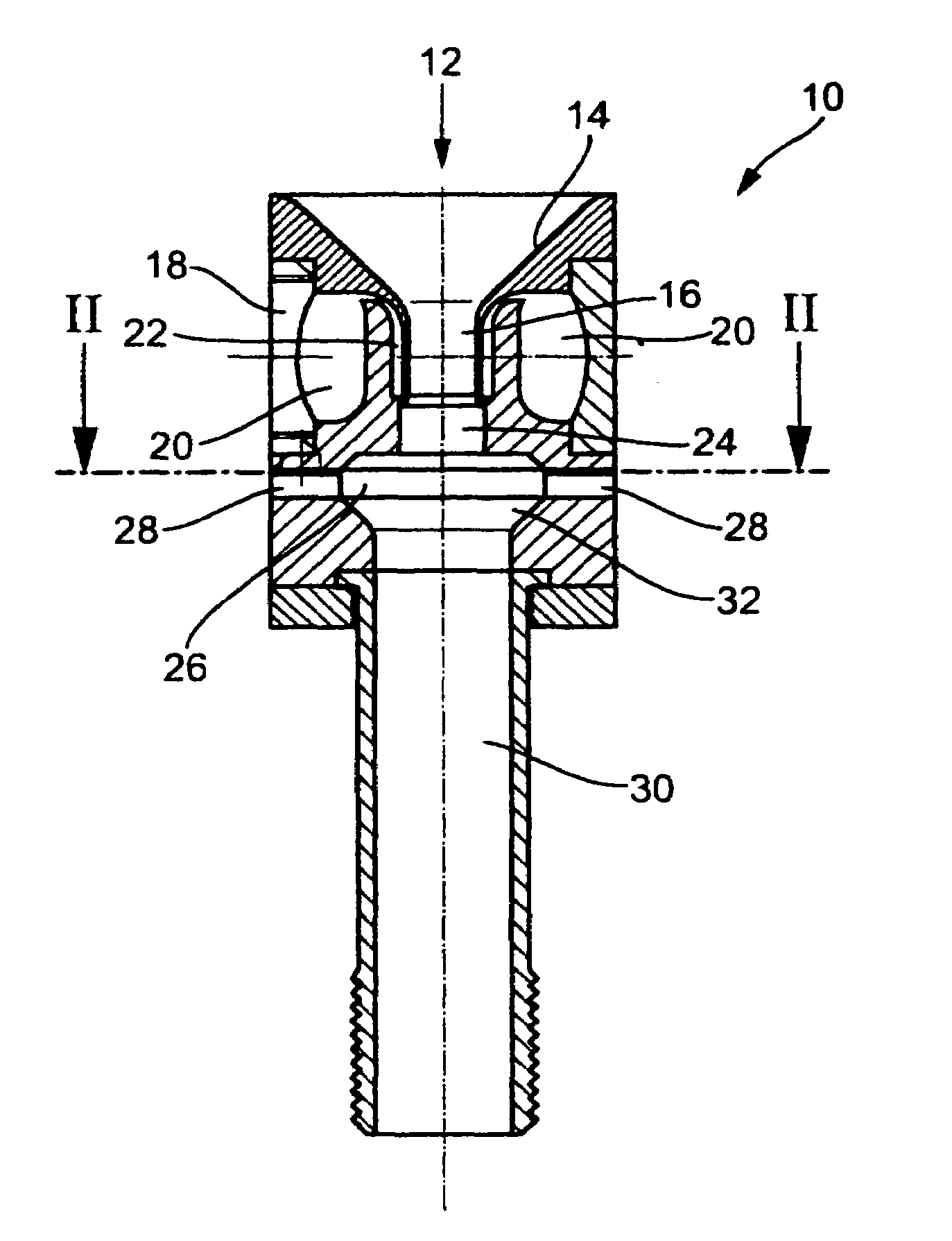
[0020]FIG. 1 shows a device, referred to in total with 10, for generating a homogeneous powder-air mixture which is used e.g. in a dusting means for dusting printed paper sheets in a printing machine. Powder is thereby supplied from a supply container (not shown) via a dosing means (not shown) in the direction of arrow 12. This powder falls into a funnel 14 which terminates in a suction line 16. Reference numeral 18 designates a line nozzle for supplying compressed air. This line nozzle 18 terminates in an annular distribution space 20 in which the compressed air is uniformly guided into an annular space 22. The compressed air in this annular space 22 is downwardly deflected around the suction line 16, thereby forming an envelope jet. The suction line 16 terminates in this envelope jet with the consequence that powder from the funnel 14 and the suction line 16 is carried along by the envelope jet.

[0021]This mixture of powder and air has a flow velocity but is still inhomogeneous and...


PUM

PropertyMeasurementUnit
Pressureaaaaaaaaaa
Angleaaaaaaaaaa
Flow rateaaaaaaaaaa

Abstract

The invention relates to a device for generating a homogeneous powder-air mixture comprising a pressure section and a suction section, wherein the two sections merge in an outlet, wherein the pressure section terminates in an orthogonal direction in the suction section in an ejector-like manner, the suction section being open towards the surroundings. The invention also relates to a method for generating a homogeneous powder-air mixture.

Description

[0001]This application is the national stage of PCT / EP2005 / 009038 filed on Aug. 22, 2005 and also claims Paris Convention priority of DE 10 2004 043 411.5 filed on Sep. 2, 2004.BACKGROUND OF THE INVENTION[0002]The invention relates to a device for producing a homogeneous powder-air mixture, the device comprising a pressure section and a suction section, wherein the two sections merge in an outlet. The invention also relates to a method for generating a homogeneous powder-air mixture.[0003]Devices for mixing powder and air are conventionally known. Powder-air mixtures of this type are required i.a. in the printing industry for dusting freshly printed sheets. DE 199 37 557 A1 discloses a device of this type, wherein powder and air are mixed. The powder-air mixture generated by this device is, however, not sufficiently homogeneous.[0004]Other devices have been proposed for producing a more homogeneous mixture. EP 0 636 405 A2 e.g. discloses a device for mixing a solid matter jet with g...

Claims


Application Information

Patent Timeline
IPC IPC(8): B65G53/46B01F23/30B01F33/40
CPCB01F3/06B01F5/0413B41F23/06B05B7/1404B01F5/0428B01F2015/0221Y10T137/4891B01F23/30B01F25/31242B01F25/312B01F35/715
Inventor HAAS, RAINER
Owner WEITMANN & KONRAD
Why Eureka
Try Eureka