Star configuration optical resonator

a technology of optical resonators and star configurations, which is applied in the direction of optical resonator shape and construction, laser details, active medium shape and construction, etc., can solve the problems of limiting the resonator's ability to produce near diffraction-limited beam quality, increasing the overall length and weight of the resonator, and the cumulative beam propagation path length required for the laser to travel between ama modules adds significantly to the overall length and weight of the r

Active Publication Date: 2009-10-27
THE BOEING CO
View PDF13 Cites 1 Cited by
  • Summary
  • Abstract
  • Description
  • Claims
  • Application Information

AI Technical Summary

Benefits of technology

[0007]The present invention is to an AMA SSL optical resonator in which the optical elements are positioned around the perimeter of the optical cavity in a manner which provides the laser radiation within the cavity with a propagation path trajectory having a low angle of incidence at each AMA active surface, thereby permitting higher efficiency AMA cooling and higher output power per unit size than prior art AMA SSL resonators.
[0012]The common tier and cascaded optical resonator configurations of the present invention are capable of providing a high power SSL signal within a structure which optimizes both weight and volume efficiencies while further optimizing AMA cooling. It does this by causing the laser light to travel among the resonator's optical elements in a modified star polygon propagation path, which provides the light with a low optical angle of incidence at each AMA surface. The result is an optical resonator structure which is more easily transportable.

Problems solved by technology

These temperature gradients can distort the optical phase front of the laser and degrade beam quality, thereby limiting the resonator's ability to produce near diffraction-limited beam quality (BQ).
In linear resonators the cumulative beam propagation path length required for the laser to travel between AMA modules adds significantly to the overall length and weight of the resonator.
Alternatively, circular optical resonators present a high angle of incidence to the laser radiation at the gain medium optical surface, making water cooling of the AMA more complex.
This too adds size and weight to the resonator structure.
The larger size and weight of the linear and circular resonator structures also cause them to lose optical bench stiffness, further contributing to resonator instability.

Method used


Image

  • Star configuration optical resonator
  • Star configuration optical resonator
  • Star configuration optical resonator

Examples


Embodiment Construction

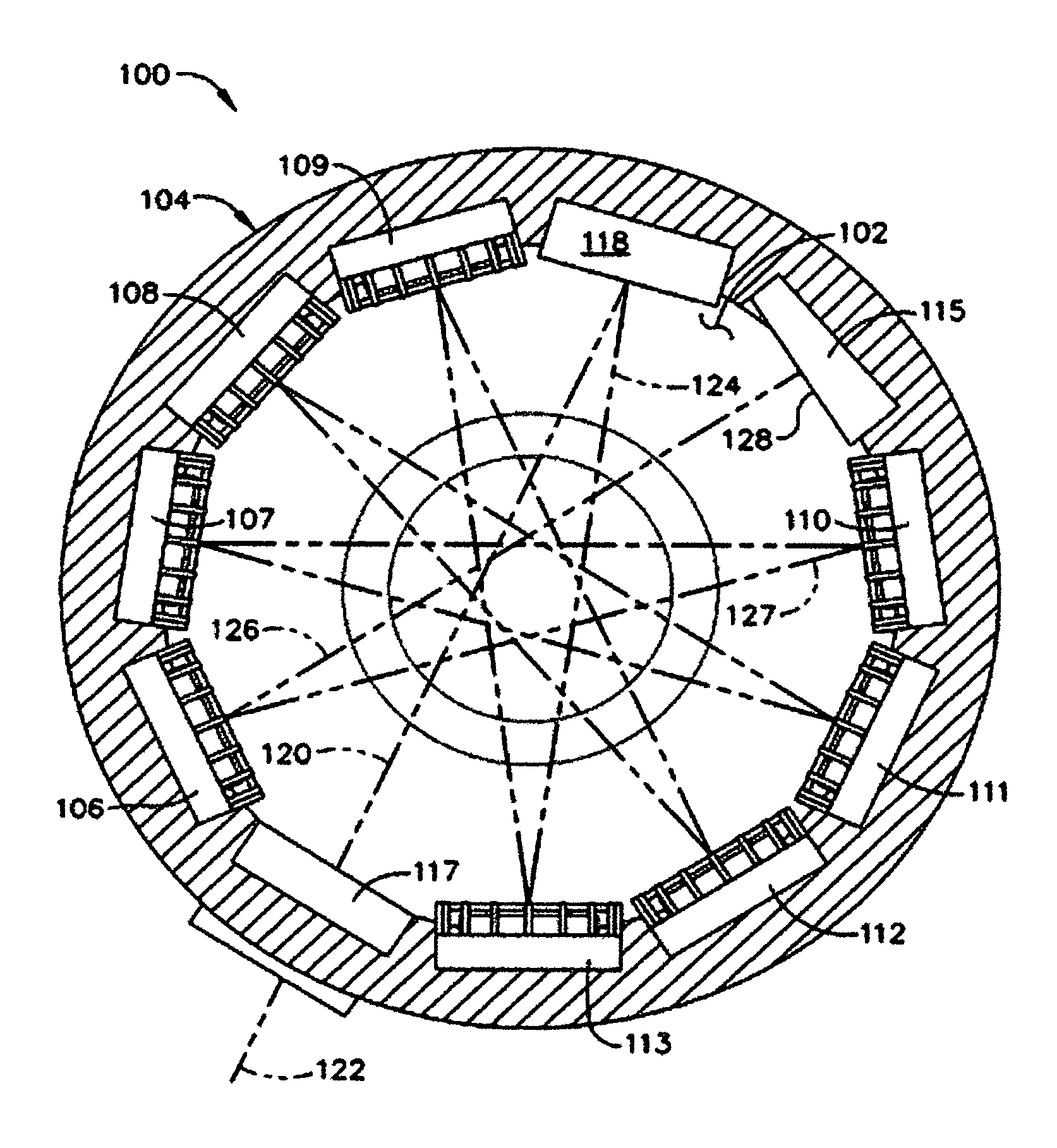
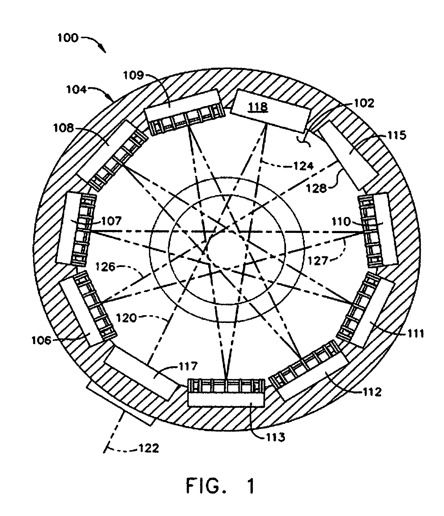
[0021]The present invention is to an optical resonator capable of providing a HAP SSL in a more highly compact resonator structure than that available in the prior art. The result is a lighter weight, smaller sized device that is more suitable for portable applications than prior art optical resonators. It does this with a cavity arrangement of optical elements that present the laser radiation with shorter transmission distances between elements, and which present the radiation itself at a more shallow angle of incidence to the element's active surface. The shorter transmission distances make the resonator less sensitive to mirror alignment and more practical for integration onto mobile platforms. The shallow angle of incidence permits more efficient AMA cooling, thereby allowing for greater output power while maintaining good BQ.

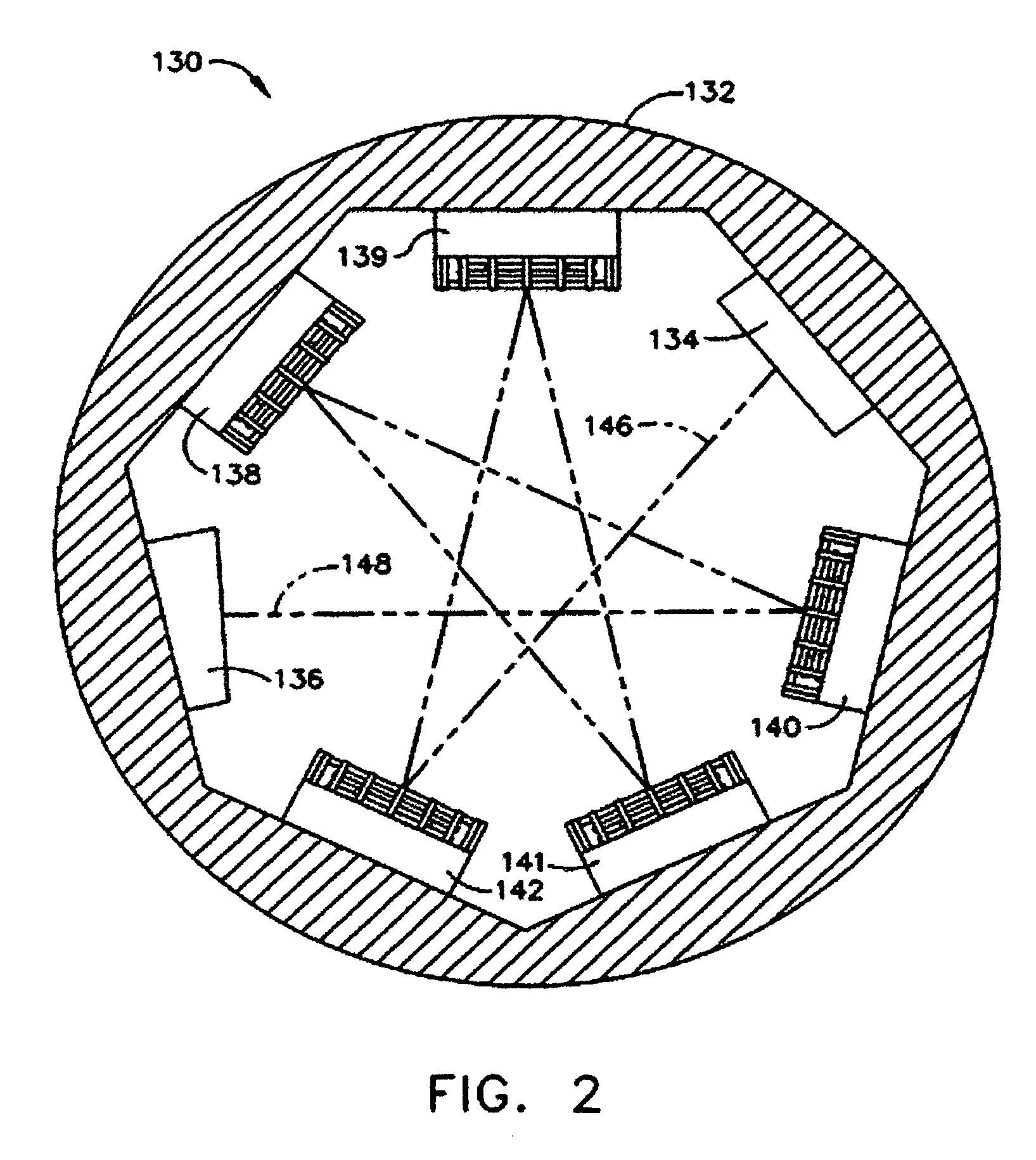
[0022]These benefits are realized by providing the cavity with a laser radiation propagation path which is substantially in the form of a {P, Q} star polyg...


PUM


Abstract

An optical resonator has an internal cavity with an output coupler, an end mirror, and one or more active mirror amplifiers (AMAs) that are arranged in a manner to form a laser radiation propagation path within the cavity which substantially has the form of a star polygon trajectory.

Description

TECHNICAL FIELD[0001]This invention relates to the field of pumped solid state lasers (SSLs), and more particularly to pumped SSLs which use active mirror amplifier (AMA) modules as the laser gain medium.BACKGROUND ART[0002]As known, a solid-state laser (SSL) extracts coherent light from an inverted population of neodymium, ytterbium, or other suitable ions doped into the SSL gain medium of an optical resonator. This population inversion is created by optically exciting the dopant ions by pumping them with optical radiation at wavelengths shorter than the laser wavelength. The pumping raises the laser atoms to an upper energy level, thereby increasing the laser power. The pumping, however, also generates heat that creates transverse temperature gradients within the SSL gain medium. These temperature gradients can distort the optical phase front of the laser and degrade beam quality, thereby limiting the resonator's ability to produce near diffraction-limited beam quality (BQ).[0003]...

Claims


Application Information

Patent Timeline
Patent Type & Authority Patents(United States)
IPC IPC(8): H01S3/091H01S3/08
CPCH01S3/025H01S3/09415H01S3/08H01S3/07H01S3/0604
Inventor DICK, DAVID
Owner THE BOEING CO
Why Eureka
Try Eureka