Scanner system and method for mapping surface of three-dimensional object

a three-dimensional object and scanning system technology, applied in dental surgery, instruments, dental tools, etc., can solve the problems of significantly more computational workload for cumulative registration, and achieve the effects of high degree of precision, and high degree of precision

Active Publication Date: 2009-10-27
ORAMETRIX
View PDF16 Cites 163 Cited by
  • Summary
  • Abstract
  • Description
  • Claims
  • Application Information

AI Technical Summary

Benefits of technology

[0024]The scanning system enables three-dimensional surface information to be obtained with a very high degree of precision. Moreover, the scanning system can be used without requiring precise movement of the scanner, or requiring the object under scrutiny to be fixed in space. The scanner is able to generate precise three-dimensional surface information by simply moving the scanner over the surface of the object, such as by hand, in any manner that is convenient for the user, even if the object moves in any random direction during scanning within reasonable limits. Thus, the scanner can be used to capture the surface of a patient's dentition in a few minutes, even if the patient moves his / her head or jaw while the scanning is occurring. Precise knowledge of the spatial relationship between the scanner and the object is not required.
[0031]In yet another embodiment of the invention, a separate transmitter and a separate receiver are used in place of a transceiver.In yet another embodiment of the invention, the static mirror is heated to prevent fogging in the in-vivo scanning application.
[0033]In an orthodontic embodiment of the scanner, it may be desirable to reduce the amount of equipment that is positioned proximate to the patient's chair. Hence, considerable latitude is possible in the configuration of the scanning system in terms of where processing, scanner illumination, or other functions are housed. Ideally, the scanner is connected via a cable or wireless communication medium to a base station for the scanner, the scanner workstation, and other equipment so as to provide the minimum amount of interference with the act of scanning at the chair side. The cable could for example be suspended from the ceiling.
[0034]In an orthodontic embodiment of the invention, the collimator, the MEMS device, the beam splitter, the lenses, the coupler and the additional static mirror are contained in a housing sized and shaped to be held in a human hand. The scanner is preferably capable of in-vivo scanning anatomical structures in the mouth. It is also suitable for scanning a plaster model of the teeth or even an impression of the teeth. All of these objects contain the same surface information, which is captured by the scanner. In a preferred embodiment, the processing of the images is performed in the scanning node, or other remote processing unit such as a back office orthodontic server. Alternatively, the computer processing of the images can be shared between two or more processing units, e.g., between the scanning workstation and the back office server, in order to reduce the amount of processing time. Furthermore, the scanning workstation may include a monitor operatively connected to the processing unit. The monitor displays three-dimensional images of the scanned object either during or after the processing unit has derived the spatial information of the object from the captured images.

Problems solved by technology

The disadvantage is that cumulative registration can be significantly more computationally intensive.

Method used


Image

  • Scanner system and method for mapping surface of three-dimensional object
  • Scanner system and method for mapping surface of three-dimensional object
  • Scanner system and method for mapping surface of three-dimensional object

Examples


Embodiment Construction

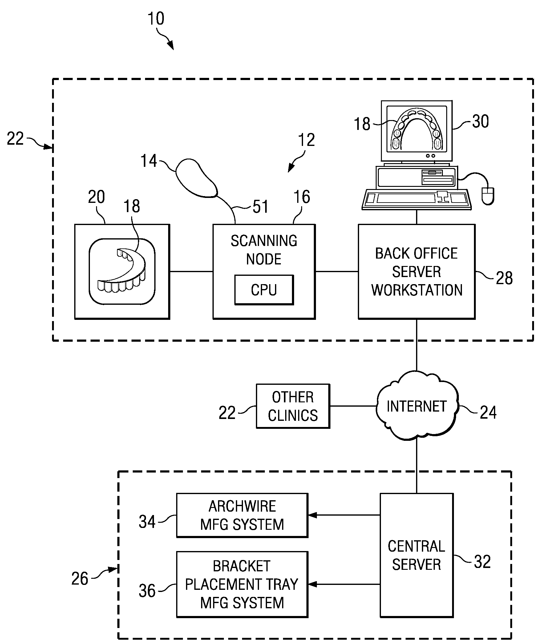
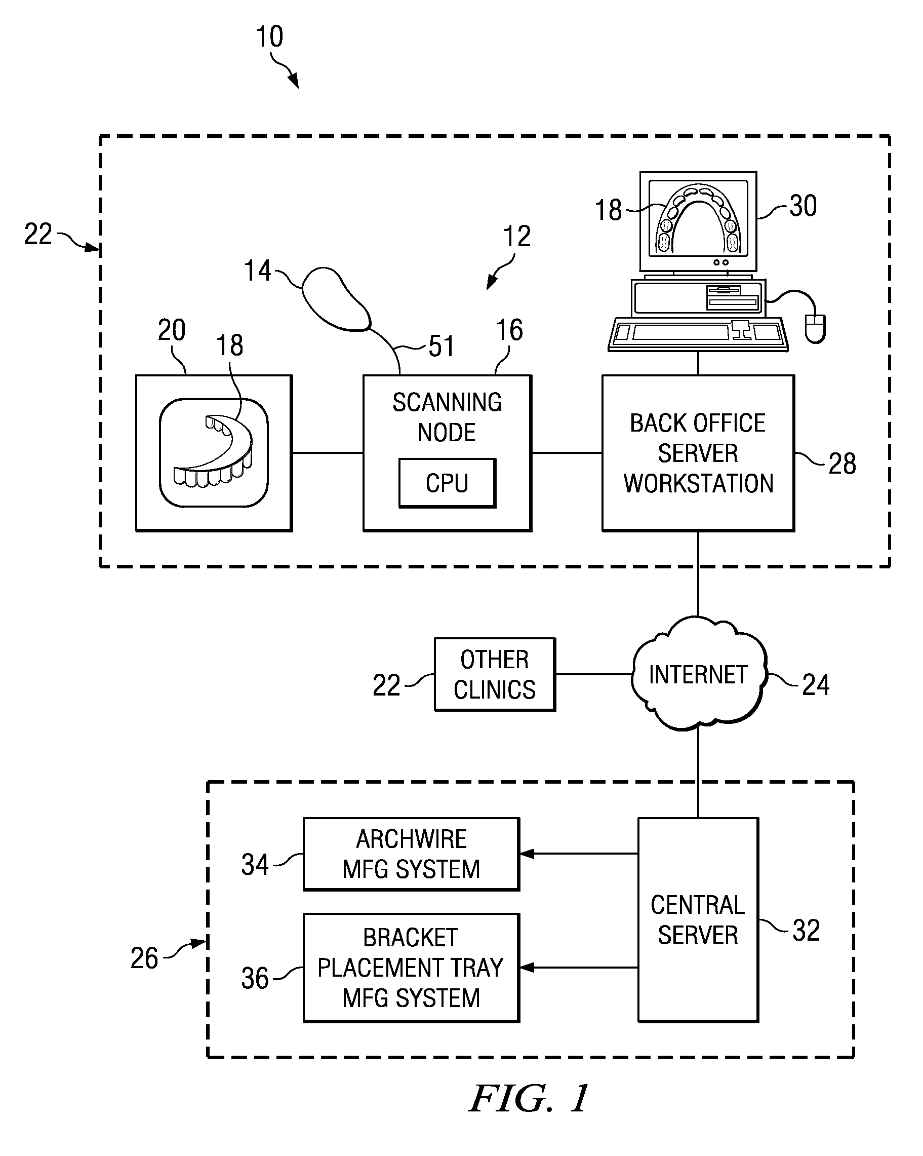
[0057]FIG. 1 is an illustration of an orthodontic care system 10 incorporating a scanner system 12 in accordance with a representative embodiment of the invention. The scanner system 12 includes a hand-held scanner 14 that is used by the orthodontist or his or her assistant to acquire three-dimensional information of the dentition and associated anatomical structures of a patient. The images are processed in a scanning node or workstation 16 having a central processing unit, such as a general-purpose computer. The scanning node 16, either alone or in combination with a back-office server 28, generates a three-dimensional computer model 18 of the dentition and provides the orthodontist with a base of information for diagnosis, planning treatment, and monitoring care for the patient. The model 18 is displayed to the user on a monitor 20 connected to the scanning node 16.

[0058]As noted above, the scanner system 12 described in detail herein is optimized for in-vivo scanning of teeth, o...


PUM

PropertyMeasurementUnit
frequencyaaaaaaaaaa
wavelengthaaaaaaaaaa

Abstract

A scanning system is disclosed including a hand-held scanning device for capturing three-dimensional information of an object. The scanner system includes a high-speed transceiver having a high-speed laser light source, a high frequency MEMS oscillating scanning mirror and software for frame registration. Laser based range finding technique is used to map the scanned object. MEMS oscillating at high speed enables rapid and accurate scanning of an object. The scanning can be performed without knowledge or even precise control of the position of the object relative to the scanner. Random movement of the object during scanning is also possible. The scanner can be used for a variety of purposes, including medical and industrial purposes. The illustrated embodiment is in-vivo scanning of human teeth for purposes of orthodontic treatment planning and diagnosis. Several benefits from the scanner are possible: much higher resolution of the scanned object, improved acquisition speed of the three-dimensional information of the surface of the object to be mapped, and the improvement in virtual image clarity.

Description

BACKGROUND OF THE INVENTION[0001]A. Field of the Invention[0002]This invention relates generally to a system for scanning a three-dimensional object. The scanning system utilizes a laser-based range finding technology coupled with a scanning mirror, such as a Micro-Electro-Mechanical Systems (MEMS) mirror, oscillating at a high frequency, and a high-speed transceiver. The scanning system acquires surface information of the scanned object and generates an accurate three-dimensional computer model of the object from the captured information.[0003]The inventive scanning system and method can be used to analyze the surface and three-dimensional shape of virtually any three-dimensional object, including work pieces and manufactured objects, art objects, archaeological artifacts, and large scale structures such as rooms and buildings. The invention is particularly useful in medical-related applications, including orthodontics, and the present document discusses the invention in the contex...

Claims


Application Information

Patent Timeline
Patent Type & Authority Patents(United States)
IPC IPC(8): G06K9/00A61C3/00G02F1/11
CPCA61C7/00A61C13/0003A61C7/002G01B11/24
Inventor LIU, YONGQIANGETTO, PHILLIP
Owner ORAMETRIX
Why Eureka
Try Eureka