Plastic quick-snap centerbearing isolator mount and method of manufacturing and assembling same

a technology of center bearing and isolator, which is applied in the direction of elastic bearings, rigid support of bearings, transportation and packaging, etc., can solve the problems of large force required to press the inner sleeve, the overall cost of manufacture, and the weight of known isolator mount assemblies, etc., to facilitate the attachment of molded rubber/elastomer isolators

Active Publication Date: 2009-11-03
CONTITECH USA INC +1
View PDF11 Cites 31 Cited by
  • Summary
  • Abstract
  • Description
  • Claims
  • Application Information

AI Technical Summary

Benefits of technology

[0004]One drawback associated with the current industry standard is that a large force is required to press fit the inner sleeve with the mold bonded isolator into the outer bracket. There is also a concern with the potential that the mold bonded isolator / inner sleeve may separate or axially move relative to the outer bracket. Moreover, known isolator mount assemblies have significant weight, and a need also exists to improve the overall cost to manufacture and assemble.
[0006]Accordingly, a need exists for an improved vibration isolator and method of manufacture / assembly that meets or exceeds the performance characteristics of known arrangements, and overcomes various problems of the prior art and methods of manufacture / assembly in a simple, economical way, and in a manner that is easy to manufacture.SUMMARY OF THE INVENTION
[0007]An improved resilient mounting or centerbearing isolator mount is provided that incorporates an insert that facilitates attachment of a molded rubber / elastomer isolator to an outer bracket.
[0014]A primary benefit of the invention resides in the increased manufacturing throughput by removing the existing large outer bracket from the rubber / elastomer mold and replacing it with a smaller molded plastic component, i.e., increased number of cavities in the mold.
[0015]Another advantage is associated with the reduced force required to assemble the mold bonded isolator / inner sleeve subassembly to the outer bracket.
[0016]Yet another advantage results from eliminating galvanic corrosion between selected components of the vibration isolator assembly.

Problems solved by technology

One drawback associated with the current industry standard is that a large force is required to press fit the inner sleeve with the mold bonded isolator into the outer bracket.
Moreover, known isolator mount assemblies have significant weight, and a need also exists to improve the overall cost to manufacture and assemble.

Method used


Image

  • Plastic quick-snap centerbearing isolator mount and method of manufacturing and assembling same
  • Plastic quick-snap centerbearing isolator mount and method of manufacturing and assembling same
  • Plastic quick-snap centerbearing isolator mount and method of manufacturing and assembling same

Examples


Embodiment Construction

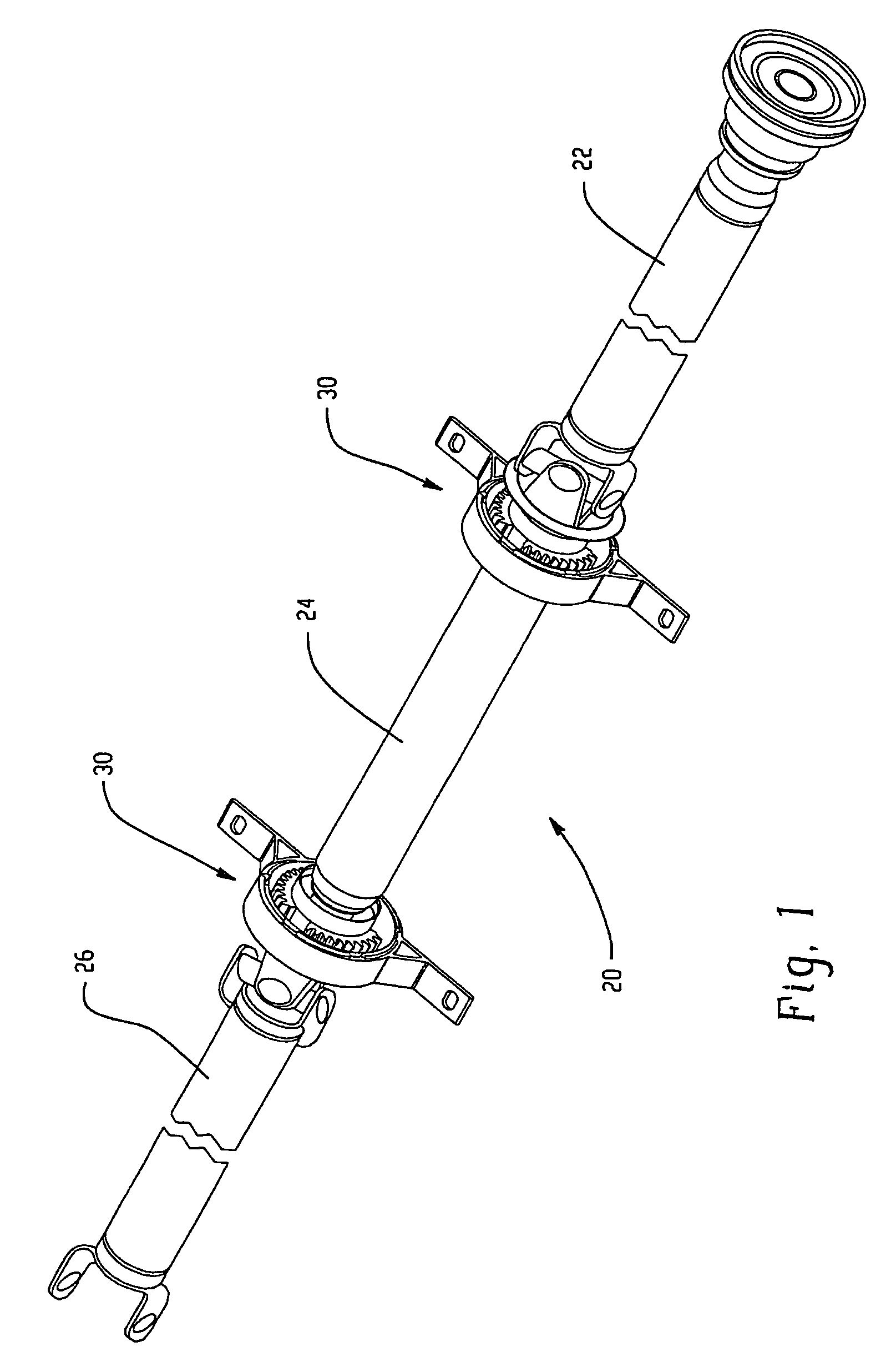
[0030]Turning first to FIG. 1, a rotary shaft such as a propshaft 20 is shown and includes three distinct portions, namely, front propshaft 22, a mid propshaft 24, and a rear propshaft 26. These portions are assembled together in a known manner to transmit rotary force from one end to the other in a manner well known in the art, the details of which are not provided herein nor necessary to a full and complete understanding of the present invention. As will be appreciated, however, the mid propshaft portion is supported adjacent opposite ends thereof by resilient mountings or bushings, more specifically referred to as center bearing isolator mount assemblies 30. As illustrated in FIG. 1, each of the bearing isolator mount assemblies is identical to the other, although variations are envisioned, some of which are described in greater detail below.

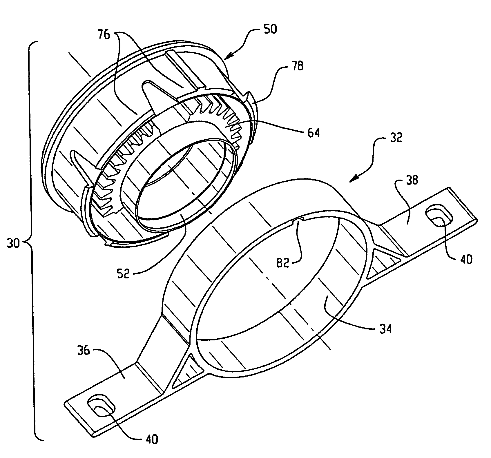
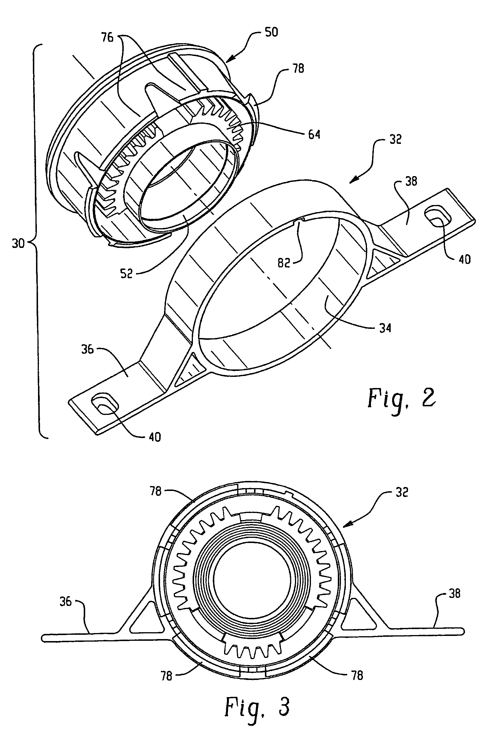
[0031]With continued reference to FIG. 1, and additional reference to FIGS. 2 and 3, the bearing isolator mount assembly includes a rigid fi...


PUM

PropertyMeasurementUnit
resilientaaaaaaaaaa
vibration dampingaaaaaaaaaa
flexibilityaaaaaaaaaa

Abstract

A resilient mount (30), such as a center bearing isolator mount includes an inner sleeve (52) into which is molded an elastomer / rubber isolator (60), and an insert (70). These components are prepared as a sub-assembly (50) and axially inserted into the opening of an outer bracket (32), whereby fingers (76) deflect radially during insertion and snap-fit radially outward once received through the bracket opening to preclude disassembly. A lower insertion force is required to assemble the components.

Description

BACKGROUND OF THE INVENTION[0001]This application claims priority from U.S. provisional application Ser. No. 60 / 484,740, filed 3 Jul. 2003, the details of which are incorporated herein by reference.[0002]This invention relates to a vibration isolator or resilient mounting, and more particularly to a center bearing isolator mount assembly for damping vibrations, for example, in a motor vehicle, as well as a method of manufacturing and assembling same.[0003]Resilient mountings or bushings generally include an outer rigid member or outer bracket formed with an aperture that receives an inner sleeve or rigid member, and a resilient, vibration damping material such as an elastomer or rubber between the outer bracket and inner sleeve. For example, it is common in the industry to form a resilient mounting of this type, often referred to as a center bearing isolator mount, by stamping an outer metal (steel) bracket in two or more separate metal stamping operations. Outer bracket components ...

Claims


Application Information

Patent Timeline
Patent Type & Authority Patents(United States)
IPC IPC(8): F16C27/00B60K17/24F16C27/06F16F1/38
CPCB60K17/24F16C27/00F16F1/38F16C27/06Y10T29/49696
Inventor LEW, JOHN G.
Owner CONTITECH USA INC
Why Eureka
Try Eureka