Floating sleeve microwave antenna for tumor ablation

a microwave antenna and floating sleeve technology, applied in the field of microwave antennas, can solve the problems of affecting the treatment effect, so as to reduce the heating tail, suppress the sar pattern tail, and reduce the heating

Active Publication Date: 2009-11-03
WISCONSIN ALUMNI RES FOUND
View PDF7 Cites 30 Cited by
  • Summary
  • Abstract
  • Description
  • Claims
  • Application Information

AI Technical Summary

Benefits of technology

[0007]The present invention suppresses the tail of the SAR pattern by use of a floating sleeve, which creates two paths of microwave propagation along the axis of the antenna from the tumor site to the skin. A dielectric along one path shifts the phase of the microwave energy to destructively interfere with the microwave energy along the second path thus effectively reducing the microwave energy near the distal portion of the antenna. The present invention may be used with other techniques for reducing the heating tail, such as suppressing shield current flow, and thus shield current heating with resonant traps and thermal insulation of the shield from tissue.

Problems solved by technology

This is because microwave power to the antenna must be limited to prevent excessive heating along a “tail” away from the tumor and along the length of the antenna.
During percutaneous treatment, this tail of heating may damage healthy tissue and burn the skin.

Method used


Image

  • Floating sleeve microwave antenna for tumor ablation
  • Floating sleeve microwave antenna for tumor ablation
  • Floating sleeve microwave antenna for tumor ablation

Examples


example

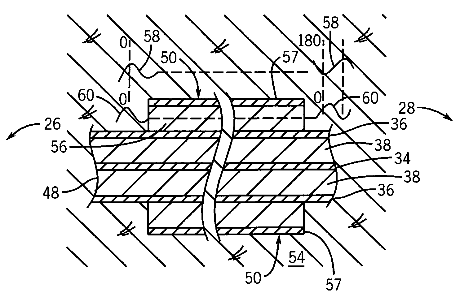
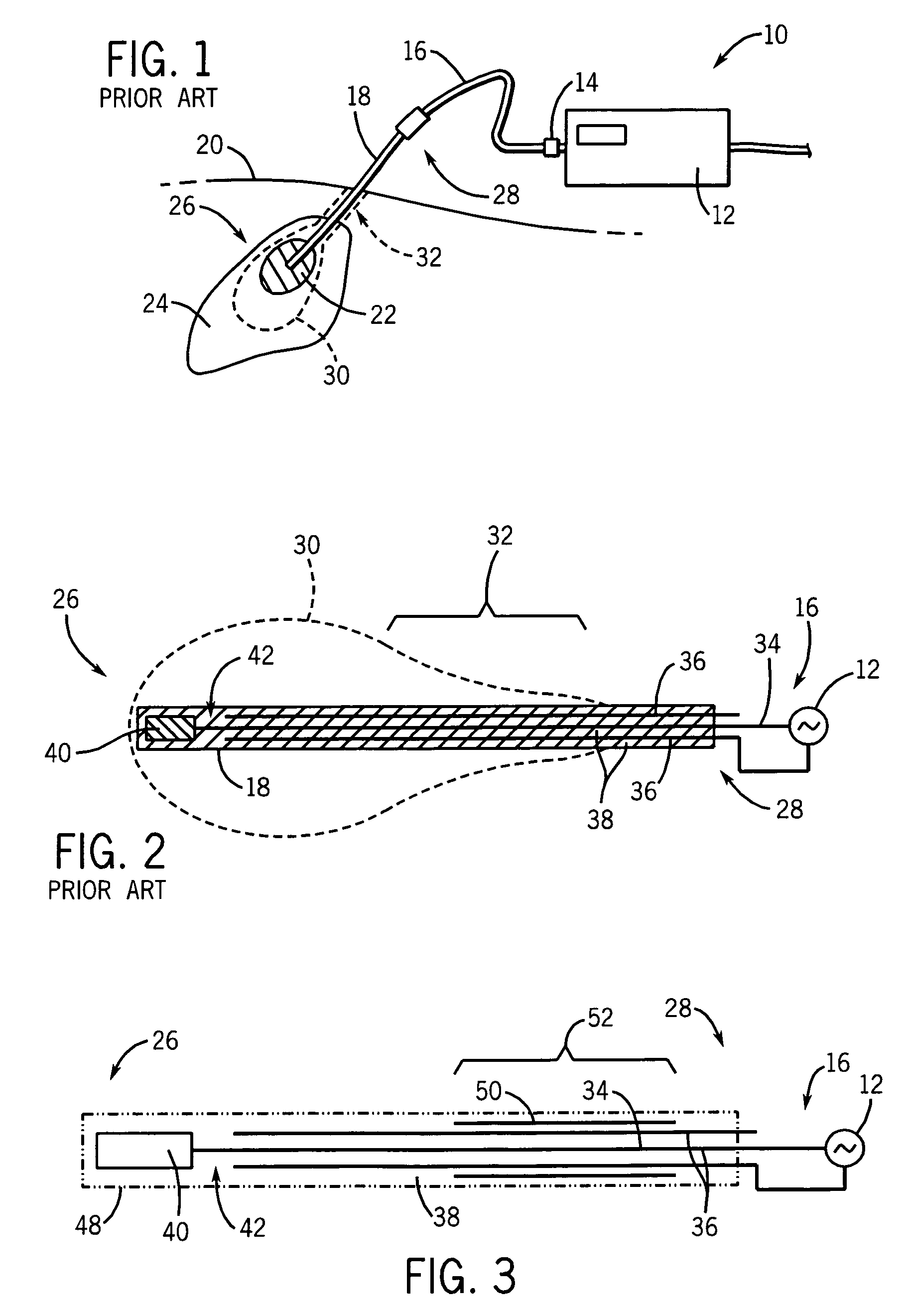
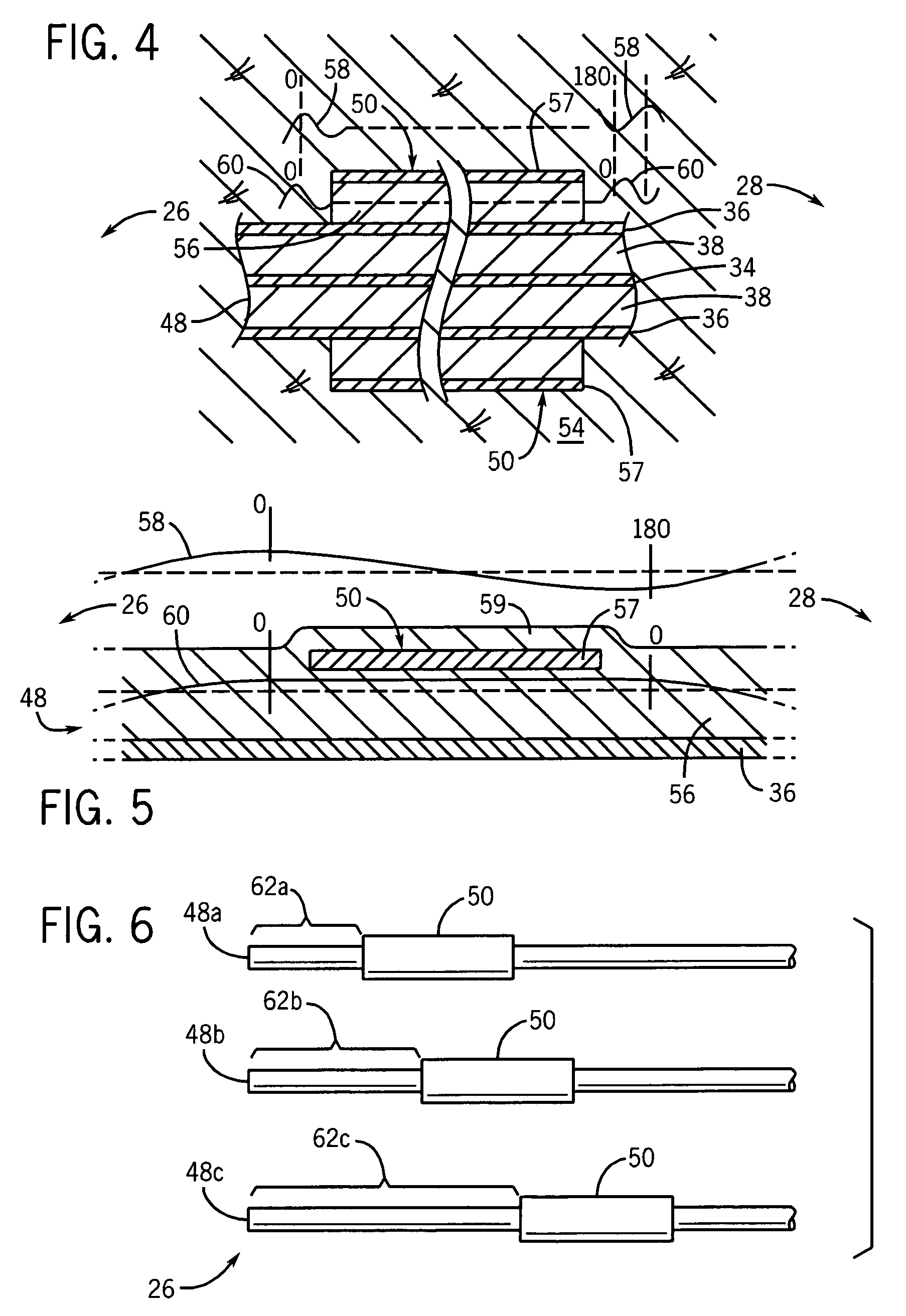
[0049]An antenna 48 constructed according to the above-described principles may be based on 50 ohm UT-085 semirigid coaxial cable wrapped with a thin layer of Teflon tape. Generally, the impedance of the antenna is set to be substantially equal to the impedance of the feed line of approximately 50 ohms. The floating sleeve 50 may be made of a section of copper tubing having a 3.2 millimeter outer diameter and a 2.5 millimeter inner diameter and approximately 19 mm in length having a proximal end about 22 mm from the proximal tip of the antenna. The whole assembly may then be rewrapped in Teflon tape and heat shrunk to the coaxial cable. The overall radius of the antenna is relatively small and suitable for intraoperative percutaneous therapies. The power supply may, for example, be a 300-watt power supply operating at 2.45 GHz.


PUM


Abstract

An antenna for microwave tumor ablation provides coaxial antenna conductors surrounded by an insulated sleeve of length and size promoting destructive interference of axial microwave energy passing inside and outside of the sleeve to limit the tail of SAR power toward the skin.

Description

STATEMENT REGARDING FEDERALLY SPONSORED RESEARCH OR DEVELOPMENT[0001]This invention was made with United States government support awarded by the following agency: NIH DK058839. The United States has certain rights in this invention.CROSS-REFERENCE TO RELATED APPLICATIONS[0002]--BACKGROUND OF THE INVENTION[0003]The present invention relates to microwave probes for tissue ablation and in particular to a microwave antenna providing improved localization during tissue heating.[0004]Microwave ablation may be used to treat tumors, for example in the liver, in patients who are not eligible for surgical removal of the tumor. In such microwave ablation, a coaxial microwave antenna is inserted into the tissue to the point of the tumor to conduct microwave energy to that location. Tissue ablation is caused by depositing energy in the region surrounding the antenna and its conversion to heat. Energy deposited into the tissue is often characterized by the Specific Absorption Rate (SAR). The SAR...

Claims


Application Information

Patent Timeline
Patent Type & Authority Patents(United States)
IPC IPC(8): A61B18/18A61F2/00A61N1/00
CPCA61B18/18H01Q9/30H01Q1/273H01Q9/20A61B18/1815A61B5/4244
Inventor YANG, DESHANBERTRAM, JOHN MICHAELCONVERSE, MARK CHRISTOPHERWEBSTER, JOHN GOODWINMAHVI, DAVID
Owner WISCONSIN ALUMNI RES FOUND
Why Eureka
Try Eureka