Gravity dependent pedicle screw tap hole guide and data processing device

a technology of pedicle screws and data processing devices, which is applied in the field of devices and methods for inserting pedicle screws into the spine, can solve the problems of limiting this range of motion, screw body or its threads being in danger of striking surrounding nerve roots, and causing damage to the surrounding nerve roots,

Inactive Publication Date: 2009-11-03
NUVASIVE
View PDF13 Cites 89 Cited by
  • Summary
  • Abstract
  • Description
  • Claims
  • Application Information

AI Technical Summary

Benefits of technology

[0012]In operation of this embodiment, the surgeon first exposes a vertebral bone and applies a Kocher clamp to the spinous process in a vertical position (where the longitudinal axis of the clamp is parallel to the acting direction of gravity) to his best visual approximation. Preferably, the guide of this embodiment is used here to make the vertical placement more accurate, by holding the shaft parallel to the longitudinal axis of the Kocher clamp while manipulating the shaft with the Kocher clamp so that when the bubble is centered under the reference mark, the surgeon knows that the Kocher clamp is in a vertical position.
[0014]Once the shaft has been placed in the desired position, the surgeon can be confident that drilling into the vertebral bone along the trajectory established by the longitudinal axis of the shaft in the desired position will result in a pedicle screw tap hole that is formed to maximize the stability of a pedicle screw subsequently screwed thereinto. The shaft can be hollow to accommodate a drill bit for this purpose, or, if the shaft is not hollow, the distal end of the drill bit can be placed against the preferred tap hole entry point of the exposed vertebral bone, and the shaft can be held parallel to the longitudinal axis of the drill bit so that the shaft and the drill bit can be angulated in parallel together until the guide indicates the drill bit is at the desired angle.
[0017]After determining the cephalad-caudad declination and medial angulation of the pedicle of interest, the surgeon places the first rotatable mounting into a rotated position at an angular offset matching the cephalad-caudad declination, and places the second rotatable mounting into a rotated position at an angular offset matching the medial angulation. During these rotations, the surgeon can view the marks to ensure that the mountings are rotated to the desired angles. Then, the surgeon positions the distal end of the shaft against the preferred tap hole entry point, and angulates the shaft until the bubble is under the reference mark. The surgeon can then safely drill the tap hole as desired along the trajectory established by the longitudinal axis of the shaft. Again, the shaft can be hollow and / or held in parallel to the drill bit as the drill bit is angulated against the preferred tap hole entry point.

Problems solved by technology

Genetic or developmental irregularities, trauma, chronic stress, tumors, and disease, however, can result in spinal pathologies which either limit this range of motion, or which threaten the critical elements of the nervous system housed within the spinal column.
Misalignment of the pedicle screws during insertion can cause the screw body or its threads to break through the vertebral cortex and be in danger of striking surrounding nerve roots.
A variety of undesirable symptoms can easily arise when the screws make contact with nerves after breaking outside the pedicle cortex, including dropped foot, neurological lesions, sensory deficits, or pain.
Unfortunately, these procedures are subject to surgeon visual approximation errors, and anatomical landmarks are different for each patient.
Further, prolonged radiation exposure to a patient is undesirable.
However, the jig has a variety of moving parts that must be adjusted and monitored simultaneously during the adjustments, making operation of the jig difficult and time consuming.
However, these systems are extremely expensive, require significant training, are cumbersome in operation, are difficult to maintain, and are not cost effective for many hospitals.
Unfortunately, this procedure is inherently reactive rather than proactive, in that the surgeon becomes aware of the misalignment after the patient exhibits a nervous reaction, and by that time the misaligned hole has been drilled.

Method used


Image

  • Gravity dependent pedicle screw tap hole guide and data processing device
  • Gravity dependent pedicle screw tap hole guide and data processing device
  • Gravity dependent pedicle screw tap hole guide and data processing device

Examples


second embodiment

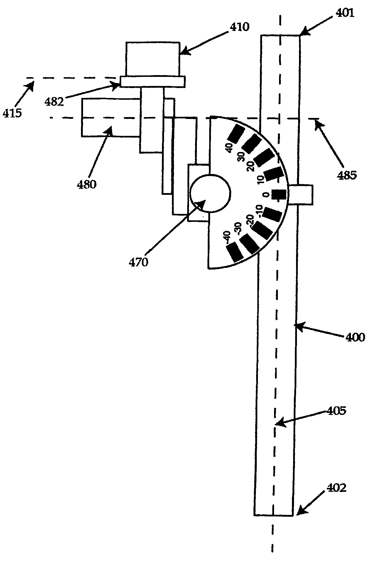
[0053]Operation of this embodiment proceeds as indicated with regard to the second embodiment, with the accelerometer 410 indicating when the accelerometer 410 is oriented level (and thus, if the rotatable mountings 470, 480 have been rotated to match the cephalad-caudad declination and medial angulation of the pedicle, that the shaft 400 is at the desired angulation).

[0054]Referring now to FIGS. 5a-c, yet another embodiment of a gravity dependent pedicle screw tap hole guide of the present invention is illustrated. The guide in this embodiment is similar structurally and functionally to the third embodiment described above, with a difference in that the accelerometer is connected to a data processing device or system, which difference will be described in detail below. More particularly, the illustrated embodiment is similar in all other respects to the third embodiment described above, and as such similar components and features are numbered similarly, except in the 500s rather th...

third embodiment

[0055]Operation of this embodiment proceeds similarly as indicated with regard to the third embodiment, with the accelerometer 510 determining when the shaft 500 is in the desired position, that is, when the angular difference between the longitudinal axis of the shaft 500 and the acting direction of gravity matches the cephalad-caudad declination (in the first plane) and medial angulation (in the second plane) of the pedicle. As noted above, however, in addition, the accelerometer 510 is in communication with the data processing device or system 526.

[0056]The data processing device or system 526 can be of any type known in the art, and is preferably able to do at least one of the following: (1) obtain signals received from the accelerometer 510, (2) interpret such signals, (3) determine desired data or information from such signals, (4) present such data or information to another device or to a user (using any presentation manner known in the art, for example, but not limited to, v...

fourth embodiment

[0061]The accelerometer 610 is similar to the accelerometer 410 described in the fourth embodiment described above, but in this embodiment does not have a display (it should be understood that in other variations of this embodiment, the accelerometer 610 can have one or more displays of its own, and even its own data processing capability separate from the data processing device or system 626 described below). Preferably as shown, at least one input connection 622 and at least one output connection 624 allow the accelerometer 610 to communicate with a data processing device or system 626. Either or both of the input connection 622 and the output connection 624 can be accomplished by any manner and / or via any device known in the art for allowing two objects to communicate, such as, for example, a wired or wireless connection. Furthermore, it some embodiments, it may desirable for only input connection(s) or only output connection(s) to be present (i.e., in which signals and / or data a...


PUM


Abstract

A gravity dependent pedicle screw tap hole guide comprises a guide shaft maintainable parallel to a drill bit during the drilling of a pedicle screw tap hole; an accelerometer associated with a reference direction and responsive to gravity to determine an angular difference between an acting direction of gravity and the reference direction; and a mounting attaching the accelerometer to the shaft and establishing a positional relationship between the reference direction and the longitudinal axis. The accelerometer is preferably in communication with a data processing device or system, which data processing device is able to use signals from the accelerometer to perform one or more actions, such as, for example, displaying the angular difference.

Description

[0001]This application is a continuation application of U.S. patent application Ser. No. 10 / 452,394 entitled “Gravity Dependent Pedicle Screw Tap Hole Guide and Data Processing Device” filed Jun. 2, 2003 now abandoned.FIELD OF THE INVENTION[0002]This invention relates generally to devices and methods for inserting pedicle screws into the spine, and more specifically to devices and methods for accurately establishing a pedicle screw tap hole drilling trajectory.BACKGROUND OF THE INVENTION[0003]The bones and connective tissue of an adult human spinal column consist of more than 20 discrete bones coupled sequentially to one another by a tri-joint complex which consist of an anterior disc and the two posterior facet joints, the anterior discs of adjacent bones being cushioned by cartilage spacers referred to as intervertebral discs. These more than 20 bones are anatomically categorized as being members of one of four classifications: cervical, thoracic, lumbar, or sacral. The cervical p...

Claims


Application Information

Patent Timeline
Patent Type & Authority Patents(United States)
IPC IPC(8): A61B17/60A61F2/00A61B17/17A61B17/58A61B19/00
CPCA61B17/1757A61B19/46A61B2019/5248A61B2019/467A61B2019/469A61B19/50A61B34/10A61B90/06A61B2034/2048A61B2090/067A61B2090/069
Inventor GOREK, JOSEF E.
Owner NUVASIVE
Why Eureka
Try Eureka