Multi-function field-deployable resource harnessing apparatus and methods of manufacture

a multi-functional, resource-harnessing technology, applied in the direction of lighting and heating apparatus, reverse osmosis, instruments, etc., to achieve the effect of minimizing air, water, ground pollution and being environmentally friendly

Inactive Publication Date: 2009-11-03
ESSIG JR JOHN R +1
View PDF37 Cites 63 Cited by
  • Summary
  • Abstract
  • Description
  • Claims
  • Application Information

AI Technical Summary

Problems solved by technology

However, this apparatus is not well suited for use as a field-deployable tool because it cannot be collapsed and re-deployed after its initial deployment, it is not multifunctional, it does not provide a means for supporting and orienting the apparatus to facilitate use in a terrestrial environment, it does not provide a means for protecting the user against accidental exposure to concentrated electromagnetic radiation, and both its mechanical structure and its means of deployment are generally too complex to allow the device to be economically produced for wide use by the general public.
Note that the mechanical attachments (tensioned cords or ties) used to deploy the reflector are generally too complex and also too great in number to permit economical construction of a device intended for general use by the public.
Also, no means is provided for supporting and orienting the apparatus in a terrestrial environment.
Further, it does not represent a portable device.
Note that the rigid support frame of the apparatus is not significantly collapsible for portage and storage, and the reflector structure contains unnecessary internal webbing, which is not economical to produce.
Also, no means is provided for adjustably supporting and orienting the apparatus in a terrestrial environment.
It does not have a means for concentrating solar energy, such as a parabolic reflector, nor any means for performing any other functions except its primary (sole) use as a capacitive aerial antenna.
Note that this apparatus is not significantly collapsible for portage and storage, and that the reflector's support structure generally inhibits or prohibits use as a broad-spectrum solar energy concentrator.
It does not represent a significantly collapsible portable device.
Note that the rigid support frame of the apparatus is not significantly collapsible for portage and storage, and the transparent membrane of the super-ambient reflector structure limits efficiency when used as a solar energy concentrator.
Note that this apparatus is not significantly collapsible for portage and storage, it is too complex to yield a sufficiently economical field-deployable tool for use by the general public, and the radome generally inhibits or prohibits use as a broad-spectrum solar energy concentrator.
Note that this apparatus exhibits an extremely clumsy or cumbersome method of cooking, and the functionality of the device is easily impaired by vapors, which, after being emitted from the items being heated or cooked within the device, may condense on the transparent membrane of the device, thereby diffusing the impinging solar radiation, thus preventing effective concentration.
Further, the device is not multifunctional.
Note that this structure is highly complex in light of its two simple functions, and it is generally not suitable for use as a terrestrial field-deployable tool.
Note, again, that the mechanical attachments (tensioned cord-ties) used to deploy the reflector are generally too complex to permit economical construction of a device intended for general use by the public.
Also, no means is provided for supporting and orienting the apparatus in a terrestrial environment.
Note that this apparatus is not significantly collapsible for portage and storage.
Note that this apparatus is not significantly collapsible for portage and storage and is not suitable for concentrating solar energy.
In short, the disadvantages of related art generally include, among others, one or more of the following limitations:(a) the device or apparatus generally is not multifunctional in nature, i.e., it is generally limited to either a single function or perhaps two or more closely related functions;(b) the apparatus is not suitably or sufficiently collapsible to permit easy transport to and from the field, or allow convenient storage when not in use;(c) the apparatus is not easily reusable or re-deployable, i.e., the apparatus cannot be collapsed after its initial deployment to facilitate portage to an alternate location or to compactly store for future use;(d) the apparatus has no lightweight collapsible means for supporting and orienting the apparatus to facilitate use in a terrestrial environment, and / or it does not employ other features to facilitate use by persons having limited experience or knowledge, such as simple well-known inflation valves;(e) the apparatus has no means for protecting the user from accidental exposure to highly concentrated electromagnetic radiation, thereby posing a safety hazard;(f) the apparatus exhibits limited efficiency when concentrating broad-spectrum solar radiation as a result of having one or more intervening layers in its optical path, such as a transparent membrane or radome;(g) the apparatus exhibits unnecessary structural complexity, thereby rendering the apparatus uneconomical to produce for wide use by the general public;(h) the apparatus is generally not suitably robust or sufficiently durable for rapid deployment into the field, such as by air drop, nor does the apparatus provide a means for easily repairing the device in the field using integral rapid-repair materials in the event of damage; and / or(i) the apparatus generally is not modular and selectably configurable by the user to perform other functions.

Method used


Image

  • Multi-function field-deployable resource harnessing apparatus and methods of manufacture
  • Multi-function field-deployable resource harnessing apparatus and methods of manufacture
  • Multi-function field-deployable resource harnessing apparatus and methods of manufacture

Examples


first embodiment

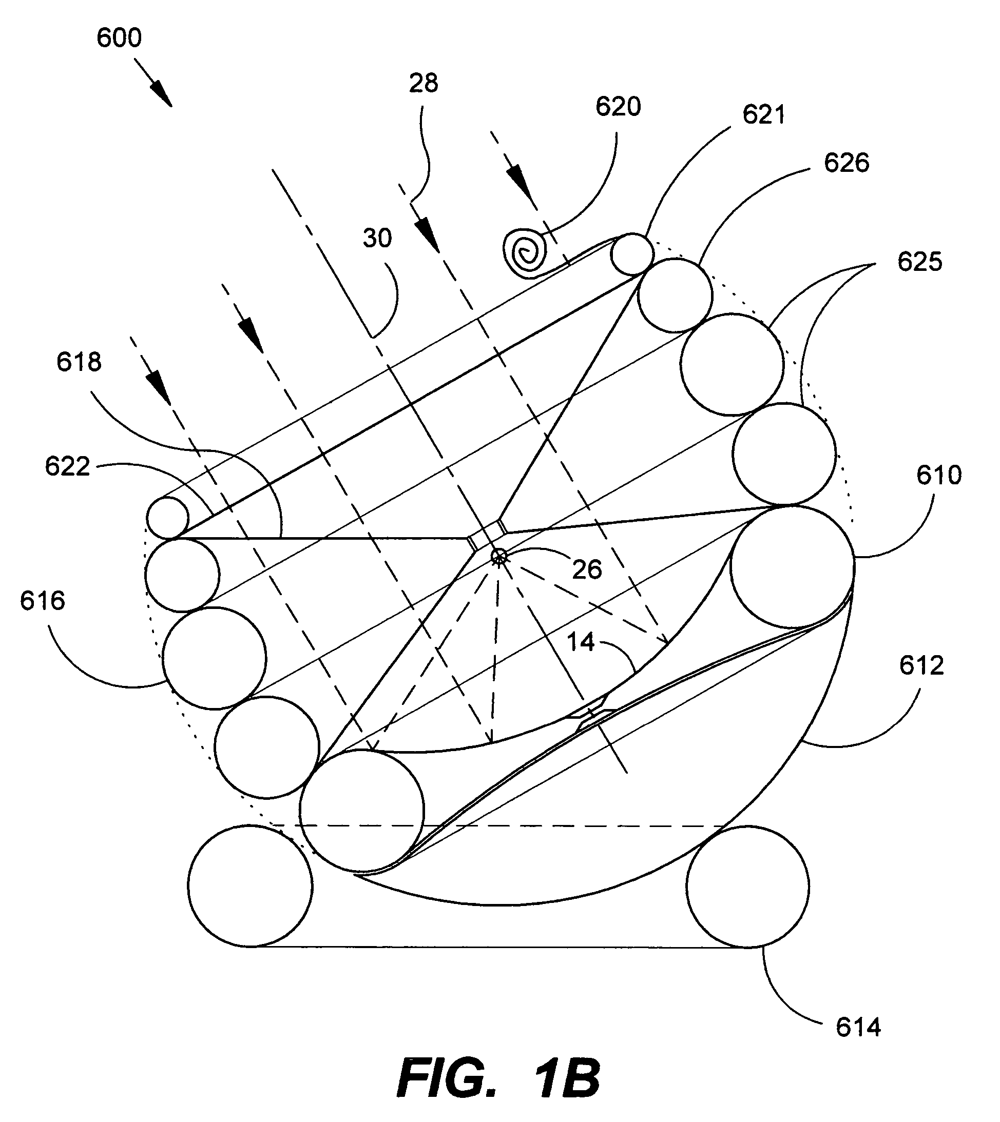
[0217]FIG. 3A depicts the first main embodiment device 610 deployed in sub-ambient mode as an electromagnetic radiant ray concentrator having the focal axis 30 of the pre-formed parabolic reflective membrane 14 oriented toward the sun (not shown). The radiant solar rays 28 are reflected by the pre-formed parabolic reflective membrane 14 to focus on an energy-absorbing object (not shown) placed at the focal point 26.

[0218]Regarding the instant device's ability to capture and concentrate electromagnetic radiation, it should first be noted that a device deployed in sub-ambient mode allows the electromagnetic rays to travel unobstructed to and from the reflector, thus providing superior capture efficiency relative to much of the related art as well as the second main embodiment of the instant invention (capture efficiency is defined herein as the portion of the incoming radiant energy that is delivered to the focal point and local surrounding area). As an example, when operated in sub-a...

second embodiment

[0226]In FIGS. 4A and 4B, the second main embodiment device 386 is illustrated as an inflated toroid or ring support element 400 supporting an upper transparent membrane 388 and a lower reflective membrane 390. The transparent membrane 388 and reflective membrane 390 provide a central reflector chamber (i.e., pressure envelope) 392 with a double parabolic convex-convex lens configuration when inflated to a super-ambient pressure. The transparent membrane 388 has a centered inflation valve 18 for inflating the reflector chamber 392; however, it is noted that the inflation valve 18 may alternatively be located at any other useful location such as in the reflective membrane 390. The inflatable toroidal support element 400 also has a valve 18 for inflation to form a rigid ring. Two valves are shown for separate inflation of the ring support 400 and the reflector chamber 392; however, it is noted that the two pressure envelopes (the toroid 400 and the reflector chamber 392) can be interc...

third embodiment

[0234]FIGS. 4K-O illustrate the construction and use of simplified alternate inflatable reflector apparatuses (third main embodiment) having only one membrane shown attached to an inflatable (or, optionally, otherwise collapsible or rigid) support element.

[0235]FIG. 4K depicts an alternate simple planar reflector or mirror apparatus 1510 provided by attaching as few as one planar (i.e., non-preformed) reflective membrane 1512 to the support ring 400. Although such an apparatus having only a single membrane is generally not operable as a single apparatus to concentrate electromagnetic energy, the apparatus 1510 can effectively serve as a highly portable self-imaging mirror, a photographic light reflector and / or diffuser, and / or a radiant electromagnetic energy heat shield (such as to shield a person, object, or other item from radiant energy emitted from a fireplace, campfire, of other radiant heat source). However, an array or plurality of such apparatuses may be used to concentrate...


PUM

PropertyMeasurementUnit
diameteraaaaaaaaaa
diameteraaaaaaaaaa
diameteraaaaaaaaaa

Abstract

A multi-function, field-deployable resource harnessing apparatus having, in its embodiments, an inflatable reflector apparatus comprising at least one manufactured parabolic mirror made from a pressure-deformable reflective covering of an inflatable ring for focusing electromagnetic energy from radio frequency radiation (RF) through the ultraviolet (UV) radiation including solar energy. A first main embodiment of the inflatable reflector apparatus generally utilizes two pressure-deformable membranes, at least one of which is reflective. A second main embodiment utilizes a reflective membrane and a transparent membrane. In addition to the reflector apparatus, the modular apparatus typically further includes modular assemblies to increase versatility facilitate use, and / or enhance safety such as, for example, a modular support and orienting assembly, a separate support ring, a safety shield or cage, a focal point support assembly, a safety cover, a safety net or mesh, and a stabilizing assembly. Portability is enhanced by complete collapsing of the inflatable device.

Description

CROSS-REFERENCE TO RELATED APPLICATIONS[0001]This application claims the benefit of U.S. Provisional Patent Application Ser. No. 60 / 620,510 filed 20 Oct. 2004. This application also claims the benefit of PCT Patent Application Ser. No. PCT / US2004 / 040479 filed 6 Dec. 2004. This application further claims the benefit of U.S. Provisional Patent Application of John R. Essig Jr and James M Essig for “Concentrating Reflector Apparatus with Safety Device and Methods of Use” filed 11 Oct. 2005, for which a serial number has not yet been assigned. This application is a continuation-in-part (CIP) of U.S. patent application Ser. No. 10 / 729,145 filed 4 Dec. 2003, which is a continuation-in-part of U.S. patent application Ser. No. 10 / 156,814 filed 30 May 2002, now U.S. Pat. No. 6,897,832 issued 24 May 2005.[0002]This application also is related in subject matter to U.S. Design Patent Applications filed 29 Nov. 2002 having Ser. Nos. 29 / 171,799, 29 / 171,800, 29 / 171,801, 29 / 171,800, 29 / 171,801, now,...

Claims


Application Information

Patent Timeline
Patent Type & Authority Patents(United States)
IPC IPC(8): H01Q15/20H01Q1/12H01Q1/34F24S23/00B01D61/06C02F1/14C02F1/44F24S23/71G10K11/28H01Q15/16
CPCA01K61/007B01D61/06C02F1/14F24J2/5271G10K11/28H01Q15/163F24J2/125C02F1/441Y02E10/47Y02E10/42Y02W10/33Y02W10/37A01K61/60Y02A20/212F24S20/80F24S23/715Y02A40/81Y02P60/60Y02E10/40
Inventor ESSIG, JR., JOHN R.ESSIG, JAMES
Owner ESSIG JR JOHN R
Why Eureka
Try Eureka