Assembly method for device employing electric ignition

a technology of electric ignition and assembly method, which is applied in the direction of electric fuzes, weapons, ammunition fuzes, etc., can solve problems such as the acquisition of defective products

Active Publication Date: 2009-11-10
DAICEL CHEM IND LTD
View PDF16 Cites 6 Cited by
  • Summary
  • Abstract
  • Description
  • Claims
  • Application Information

AI Technical Summary

Problems solved by technology

In an electric igniter having two electroconductive pins (a center pin and an eyelet pin) for electrifying a heating wire (a body that generates heat through electric resistance) or an igniter assembly using the electric igniter, positive and negative electrodes are usually connected to predetermined electroconductive pins, and when a positive or negative electrode is connected to the wrong electroconductive pin, a defective product is obtained.

Method used


Image

  • Assembly method for device employing electric ignition
  • Assembly method for device employing electric ignition
  • Assembly method for device employing electric ignition

Examples


embodiment of invention

(1) Assembly Method or Distinguishing Method in FIG. 2

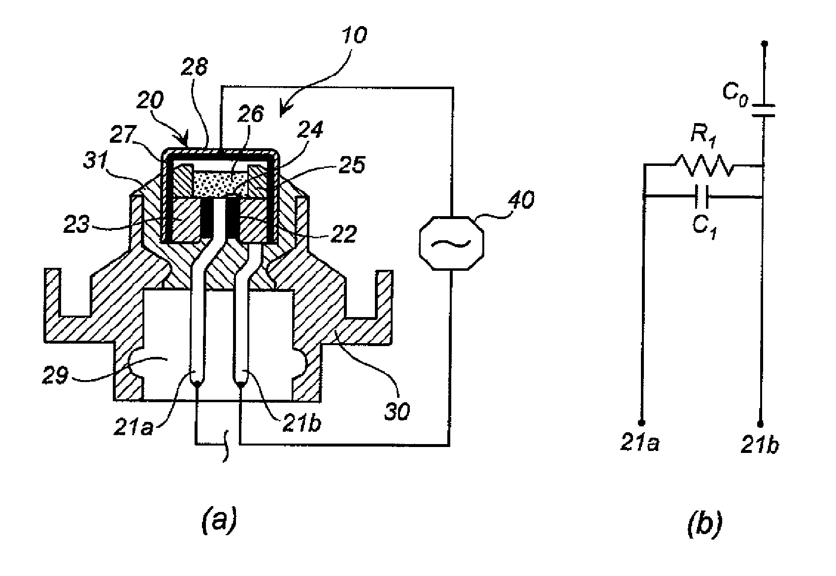
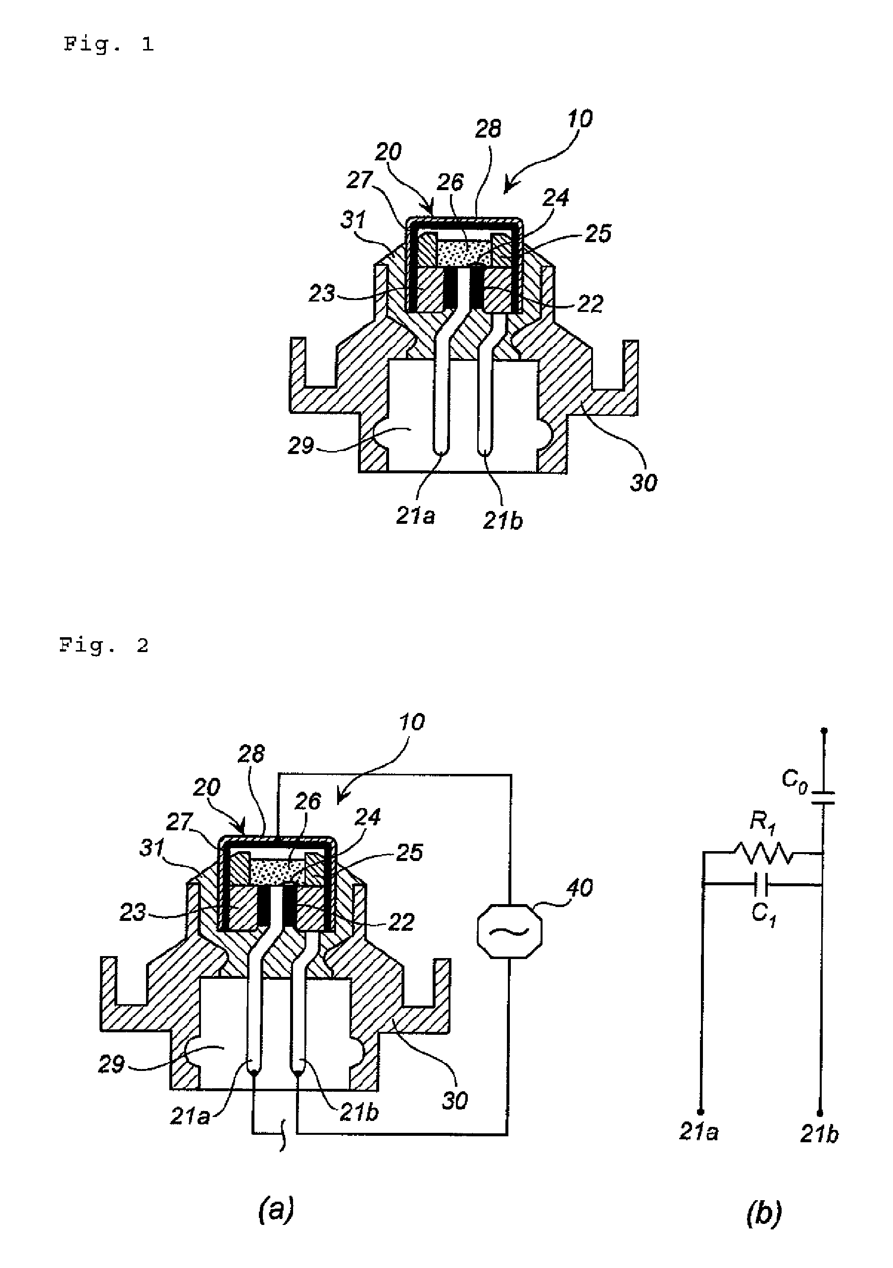
[0037]FIG. 2(a) is a sectional view of an igniter assembly for illustrating an assembly method and a distinguishing method of the present invention, and a schematic view of high-frequency resistance measurement circuits including the igniter assembly. FIG. 2(b) is an equivalent circuit diagram of high-frequency resistance measurement performed on the igniter assembly shown in FIG. 2(a).

[0038]The igniter assembly 10 is identical to the igniter assembly shown in FIG. 1, in which an ignition portion (the metallic cover 27 and the interior thereof) of the electric igniter 20 is covered by the resin cover 28 (electric insulation cover), which has an electric insulation property.

[0039]In high-frequency resistance measurement of the igniter assembly 10, a first measurement circuit having the center pin (first electroconductive pin) 21a as a terminal on one end side and the resin cover 28 as a terminal on the other end side and a second ...

example 1

Igniter Assembly of FIG. 2

[0053]The two measurement circuits (first measurement circuit and second measurement circuit) shown in FIGS. 2(a) and 2(b) were prepared, whereupon the pure resistance value (Ω) and impedance (Ω) were measured while varying the frequency, as shown in Tables 1 and 2. A “Network Analyzer, Model: 8753ES, Frequency Range: 30 kHz to 3 GHz”, manufactured by Agilent Technologies Inc., was used as the high-frequency resistance measuring device.

[0054]

TABLE 1Pure Resistance(Ω)FirstSecondFrequencymeasurementmeasurement(MHz)circuitcircuitDifference3202.500233.500−31.0004156.000173.500−17.5005116.000134.130−18.130689.250106.630−17.380773.13086.500−13.370857.88070.750−12.870945.69058.190−12.5001037.81047.940−10.130158.88016.690−7.8102013.21916.906−3.687308.1889.313−1.1254012.00011.8590.141509.5788.7970.781605.5704.2971.273705.3364.3131.023806.8756.953−0.078907.9388.914−0.9761007.0316.3400.6911504.1412.2771.8642005.4663.1512.31530077.71175.2972.414

[0055]

TABLE 2Impedance(Ω...

example 2

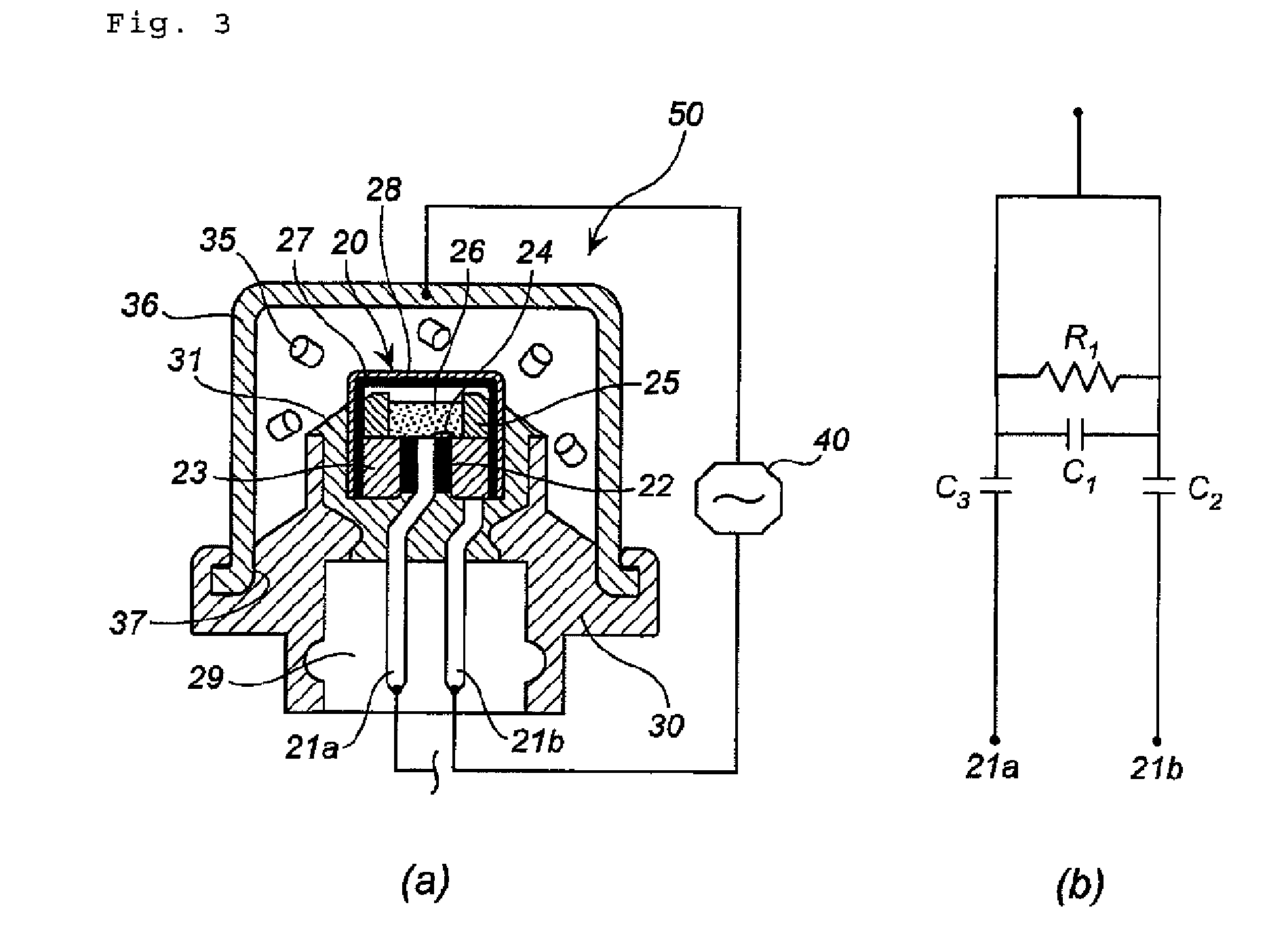
Gas Generator of FIG. 3

[0058]The two measurement circuits (first measurement circuit and second measurement circuit) shown in FIGS. 3(a) and 3(b) were prepared, whereupon the pure resistance value (Ω) and impedance (Ω) were measured while varying the frequency, as shown in Tables 3 and 4. A “Vector Network Analyzer, Model: ZVRE, Frequency Range: 10 kHz to 4 GHz”, manufactured by ROHDE & SCHWARZ, Inc. was used as the high-frequency resistance measuring device.

[0059]

TABLE 3Pure Resistance(Ω)FirstSecondFrequencymeasurementmeasurement(MHz)circuitcircuitDifference10188.560185.8102.75015111.750106.7505.0002081.96979.4372.5323048.15647.0311.1254036.62535.5161.1095028.57827.1561.4226022.90621.1091.7977019.70318.3831.3208017.10216.0861.0169015.14814.2730.87510014.00013.1090.891

[0060]

TABLE 4Impedance(Ω)FirstSecondFrequencymeasurementmeasurement(MHz)circuitcircuitDifference101633.2951601.97931.316151091.1041063.05428.05020828.691809.12319.56830560.857549.35611.50140421.799411.31010.48950335.65...


PUM


Abstract

The present invention is a method of assembling a device employing electric ignition by comprising assembling an igniter assembly in the device, the igniter assembly having an electric igniter provided with a first electroconductive pin and a second electroconductive pin, connected to a power source, the method comprising steps of:forming two measurement circuits by using the first electroconductive pin and the second electroconductive pin as a measurement terminal on one end side, respectively, and using another member provided in the igniter assembly as a terminal on the other end side with a pass through a dielectric provided in the igniter assembly,measuring pure resistances and / or impedances of the two measurement circuits, respectively, by applying a high frequency thereto separately,distinguishing the first electroconductive pin from the second electroconductive pin from a magnitude relationship (difference) between the measured pure resistance and / or impedance values, andthen, disposing the igniter assembly to the device such that the first electroconductive pin and the second electroconductive pin correspond to predetermined power source electrodes, respectively.

Description

[0001]This nonprovisional application claims priority under 35 U.S.C. § 119(a) on Patent Application No. 2006-342118 filed in Japan on 20 Dec. 2006 and under 35 U.S.C. § 119(e) on U.S. Provisional Application No. 60 / 884,562 filed on 11 Jan. 2007, which are incorporated by reference.BACKGROUND OF INVENTION[0002]1. Field of Invention[0003]The present invention relates to an assembly method for a device that employs electric ignition, such as an air bag device, and a method of distinguishing between two electroconductive pins provided in an electric igniter.[0004]2. Description of Related Art[0005]In an electric igniter having two electroconductive pins (a center pin and an eyelet pin) for electrifying a heating wire (a body that generates heat through electric resistance) or an igniter assembly using the electric igniter, positive and negative electrodes are usually connected to predetermined electroconductive pins, and when a positive or negative electrode is connected to the wrong e...

Claims


Application Information

Patent Timeline
Patent Type & Authority Patents(United States)
IPC IPC(8): F42B3/12
CPCF42B3/198
Inventor ODA, SHINGO
Owner DAICEL CHEM IND LTD
Why Eureka
Try Eureka