Reed valve assembly

a reed valve and assembly technology, applied in the field of motors, can solve the problems of increasing assembly cost, wear on the reed petals, and fatigue on the reed petals, and achieve the effects of less expensive, less assembly cost, and reduced cost of the reed valve assembly

Inactive Publication Date: 2009-11-10
MOTO TASSINARI
View PDF14 Cites 6 Cited by
  • Summary
  • Abstract
  • Description
  • Claims
  • Application Information

AI Technical Summary

Benefits of technology

[0012]The present invention is based on the realization that a reed valve assembly can be designed that is less expensive and that assembles more quickly and easily. The present invention combines the reed petals and retainer of a reed valve assembly in one part that is independently interlockable with the reed cage.
[0013]Therefore, it is an object of the present invention to reduce the cost of the reed valve assembly by reducing the number of parts therein.
[0014]It is a further object of the present invention to decrease the time of assembling the reed valve assembly.
[0015]It is a further object of the present invention to maximize the durability of the reed petals.

Problems solved by technology

One problem with the traditional 2-stroke motor reed valve is wear on the reed petals.
The resulting fatigue on the reed petals requires regular replacement of the reed petals.
The screws required are special order screws increasing the cost of assembly.
Also, with regular use and repair, the screws need to be repeatedly removed and reinserted, causing the screws and screw holes to become stripped.
This can, in turn, result in the screws falling into the motor, significantly damaging the motor.
Another problem with the reed valve 20 is assembly time.
Labor costs cause the reed valve to be unduly expensive.
While this most recent example of a traditional reed valve assembly, described in U.S. patent application Ser. No. 10 / 142,509, is an improvement over other traditional reed valves, it, nevertheless, has the problem of still requiring significant assembly time to align the reed cage, petals and retainer and to interlock them.

Method used


Image

  • Reed valve assembly
  • Reed valve assembly
  • Reed valve assembly

Examples


Embodiment Construction

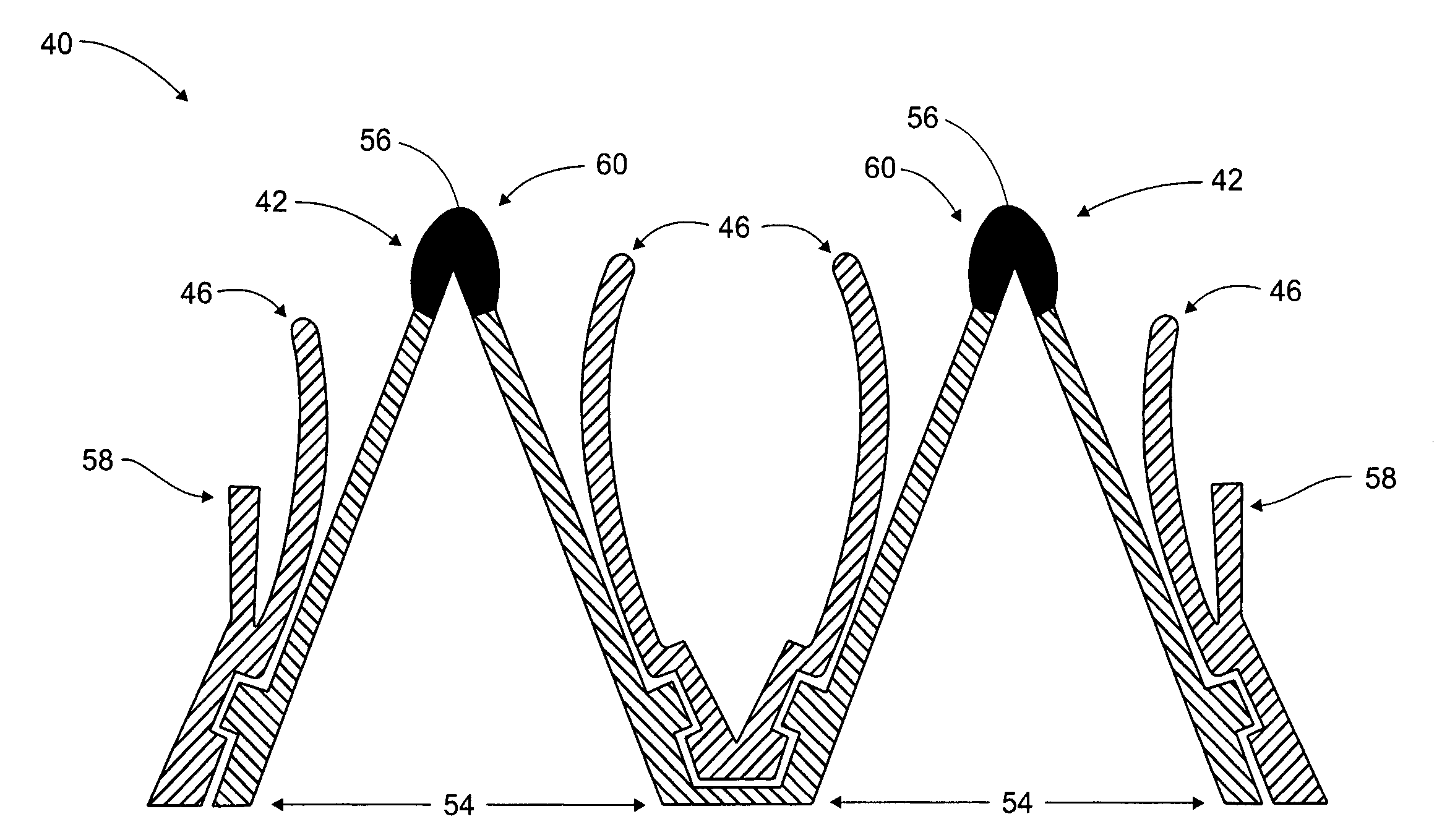
[0023]A preferred embodiment of the reed valve assembly 60 of the present invention as shown in FIG. 5 includes a reed cage 62 and a retainer 64, with reed petals 66 that are an integral part of retainer 64. The retainer 64 is independently interlockable with reed cage 62. As defined herein, independently interlockable is understood to mean that no separate parts are required to connect the retainer 64 to the reed cage 62. As implied by the term interlockable, the retainer 64 and reed cage 62 are separable.

[0024]In the same embodiment, as shown in cross-section in FIG. 7, the reed petals 66 are an integral part of the retainer 64. The retainer 64 is a flange 64a, one of several possible embodiments for the retainer 64. Tabs 68 are formed in the reed cage 62. The flange 64a is slotted 72 to accept the tabs 68, thereby interlocking the retainer 64 to the reed cage 62.

[0025]In traditional reed valve design, the retainer is, in most cases, metal such as aluminum or steel. The separate r...


PUM


Abstract

The reed valve assembly of the present invention includes a reed cage and a retainer that includes in once piece two or more reed petals. The retainer is independently interlockable with the reed cage. As defined herein, independently interlockable is understood to mean that no additional parts are required to connect the retainer to the reed cage. As implied by the term interlockable, the retainer and reed cage are separable.

Description

FIELD OF THE INVENTION[0001]The present invention relates to the field of motors. Specifically, the present invention relates to the field of reed valve assemblies. More specifically, the present invention is a reed valve assembly used in 2-stroke motors.BACKGROUND OF THE PRESENT INVENTION[0002]FIG. 1 shows an example of a traditional 2-stroke motor reed valve. The reed valve 10 includes a v-shaped base 12, pliable reed petals 14, and stoppers 16. The base is substantially hollow with a plurality of openings covered by the reed petals 14. In operation, air flows into the center of the base 12 and through the openings in the base 12, pushing the reed petals 14 back towards the stoppers 16. When the air reverses flow, the reed petals 14 press firmly against the base 12, covering the openings and substantially impeding airflow.[0003]One problem with the traditional 2-stroke motor reed valve is wear on the reed petals. A reed petal opens and closes 133 times per second if the motor is r...

Claims


Application Information

Patent Timeline
Patent Type & Authority Patents(United States)
IPC IPC(8): F16K15/16
CPCF16K15/16F02B25/00F02B2075/025Y10T137/784Y10T137/7891
Inventor TASSINARI, STEVEN M.TASSINARI, SCOTT A.
Owner MOTO TASSINARI
Why Eureka
Try Eureka