
Light bag rack for a bicycle

a bicycle and bag rack technology, applied in the field of very light bag racks, can solve the problems of time-consuming mechanical brackets, time-consuming and costly components to be effectively utilized, time-consuming and costly to make and use, etc., and achieve the effects of facilitating rod insertion, reducing the scratching of the seat frame rail, and facilitating the removal of rods

Inactive Publication Date: 2009-11-10
HUBBE RAYMOND E
View PDF15 Cites 2 Cited by
  • Summary
  • Abstract
  • Description
  • Claims
  • Application Information

AI Technical Summary

Benefits of technology

"The invention is a light bag rack for bicycles that can be easily attached and removed without tools, and made of lightweight materials like metals or ultra-light composites. The rack can be securely attached to the seat of the bicycle using the seat frame rails and includes rods that bend to securely fit the rails. The rack can be easily detached and stabilized using an attachment sleeve or a resilient contact sleeve to minimize scratching and facilitate secure and silent contact between the rack and the seat frame rails. The rack can be quickly secured to the seat post using a securing strap."

Problems solved by technology

While requiring no frame struts to a wheel axle, the assembly of Jackson nonetheless involves time consuming, heavy, complicated and costly components to be effectively utilized.
Like Jackson, however, the carrier of Goldman et al. requires time-consuming mechanical brackets that may vibrate off, and that are heavy and costly to make and use.
Like Jackson and Goldman, et al, the device of Chan et al. includes complicated, costly and heavy hardware, and includes a custom made fabric bag of limited size that must be mated to the complicated cleat and bag frame.
While Naughton's carrier is less complicated than most known bicycle carrier racks, it still involves the cost and weight of the rail hanger and abutment fork components, and the rail hanger is susceptible to vibrating and possible dislocation, etc.

Method used


Image

  • Light bag rack for a bicycle
  • Light bag rack for a bicycle
  • Light bag rack for a bicycle

Examples


Embodiment Construction

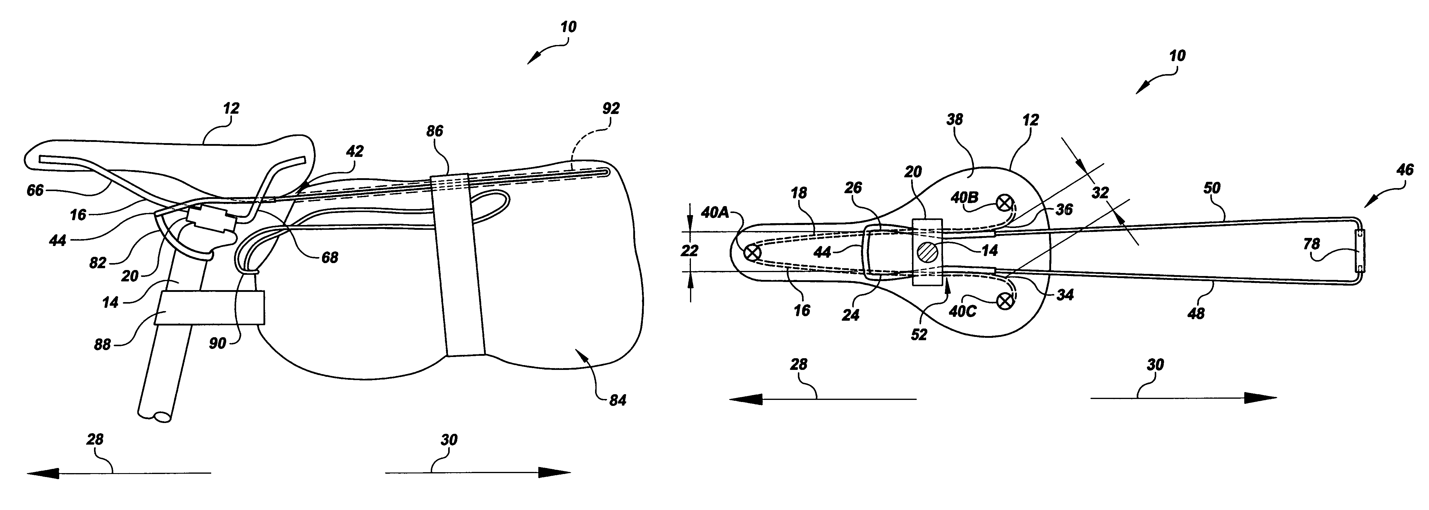
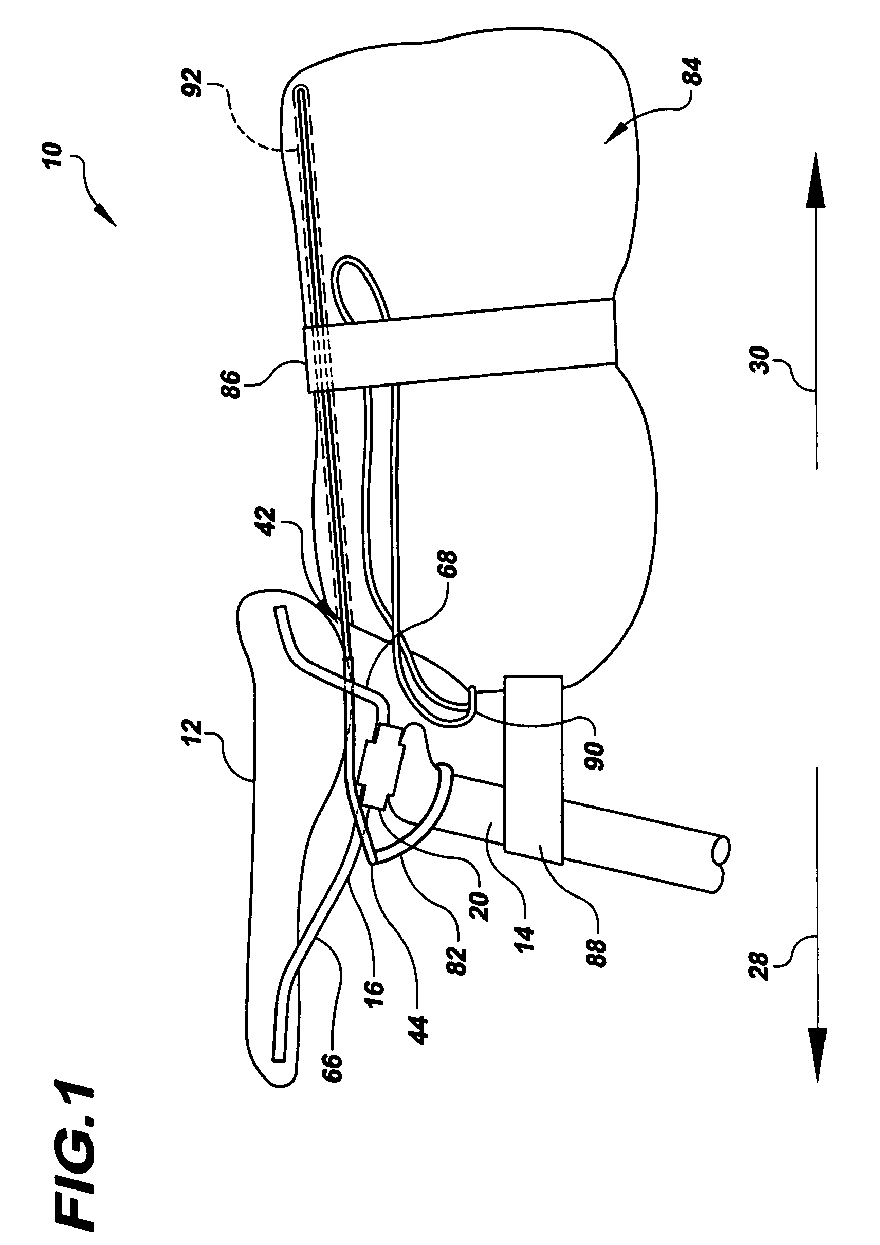
[0022]Referring to the drawings in detail, a light bag rack for a bicycle is shown in FIG. 1, and is generally designated by the reference numeral 10. The light bag rack 10 is shown in FIG. 1 secured to a seat 12 that is supported on a seat post 14. As best shown in FIG. 4, the seat 12 includes a first frame rail 16 and a second frame rail 18. A seat bracket 20 secures the frame rails 16, 18 to the seat post 14. Parallel portions of the first and second frame rails 16, 18 adjacent the seat post 14 are aligned approximately parallel to each other for a limited distance and the rails extend in a direction about parallel to a direction-of-travel axis of the bicycle (not shown) to which the seat post 14 is secured. The parallel portions of the frame rails 16, 18 define a first seat-frame distance that is represented in FIG. 4 by reference numeral 22. The first seat-frame distance 22 is a shortest distance between an exterior edge 24 of the first frame rail 16 and an exterior edge 26 of ...


PUM


Abstract

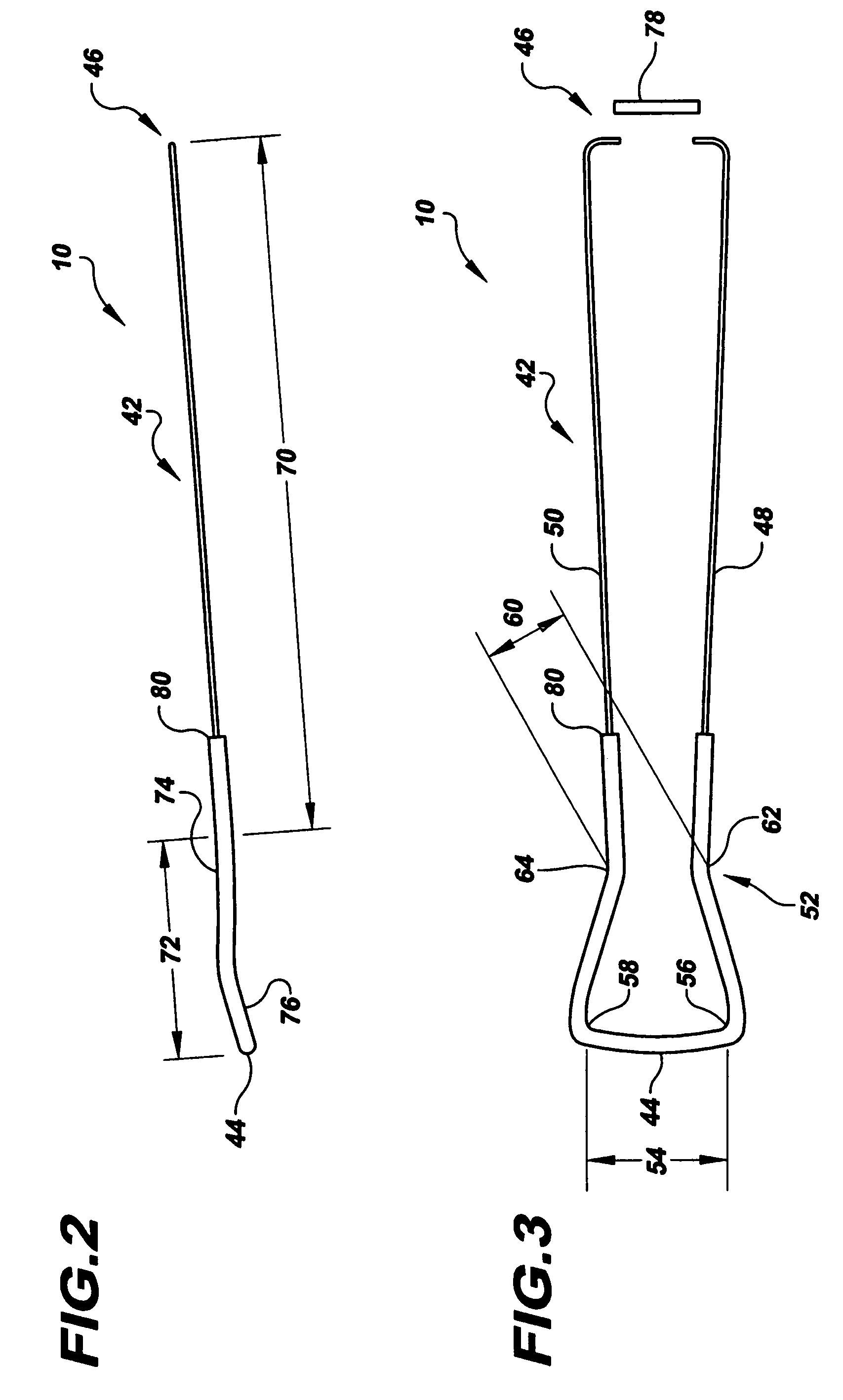
A light bag rack (10) for a bicycle includes a U-shaped frame (42) having first and second rods (48, 50) extending between a closed securing end (44) and an open mounting end (46) of the rack (10) and defining a pinch point (52) between the ends (44, 46). The rods (48, 50) are sufficiently flexible to permit the open mounting end (46) to expand around first and second bicycle seat frame rails (16, 18) forward of a seat post (14) and to pass between the seat frame rails (16, 18) rearward of the seat post (14) so that the closed securing end (44) contacts the seat frame rails (16, 18) forward of the seat post (14) to secure the rack (10) to the seat frame rails (16, 18). A load portion (70) of the rack (10) supports a utility bag (84).

Description

TECHNICAL FIELD[0001]The present invention relates to apparatus that can be secured to a bicycle to carry articles as the bicycle is driven and especially relates to a very light bag rack that can be easily secured to a bicycle.BACKGROUND ART[0002]It is well known that bicyclists often desire to bring various articles with them as they travel on their bicycles. Such articles include tire repair kits, bicycle accessories, light clothing for variable weather, food snacks, etc. For competitive bicyclists that endeavor to travel long distances at competitive speeds, it is extremely desirable that bicycle bag support structures be as light and as uncomplicated as possible. Many structures are known in the art for efficiently securing a utility bag to a bicycle.[0003]For example, a “Seat Pack Assembly” is disclosed in U.S. Pat. No. 4,566,617 that issued on Jan. 28, 1986 to Jackson which includes a U-shaped mounting bracket that receives a custom made bag. The mounting bracket, however, mu...

Claims


Application Information

Patent Timeline
Patent Type & Authority Patents(United States)
IPC IPC(8): B62J7/06B62J7/00
CPCB62J11/00B62J9/006B62J9/26B62J7/04
Inventor HUBBE, RAYMOND E.
Owner HUBBE RAYMOND E
Learn More