Rotor system for a bicycle

a technology for a rotating system and a bicycle, which is applied in the direction of braking systems, motorcycles, unicycles, etc., can solve the problems of high price of a new fork, and achieve the effects of saving construction space, simple manufacturing, and cheap components

Inactive Publication Date: 2009-11-10
GORING WOLFGANG
View PDF12 Cites 15 Cited by
  • Summary
  • Abstract
  • Description
  • Claims
  • Application Information

AI Technical Summary

Benefits of technology

[0005]It is preferable that the chamber in the handle stem is contained, at least in segments, within the solid material of a body, where it preferably ends in a bushing upon which a ring as the other component of the rotor is supported and which ends in a connection opening. The ring then preferably contains another chamber, which is semi-open and which surrounds the connection opening like a ring, such that a fluid connection can be achieved with a few, simple to manufacture and thus cheap components.

Problems solved by technology

This particular advantageous, if a retrofit is contemplated, because in those cases the fork shaft is already sawed off rather short and the purchase of a new fork is expensive due to the suspension-induced high costs.

Method used


Image

  • Rotor system for a bicycle
  • Rotor system for a bicycle
  • Rotor system for a bicycle

Examples


Embodiment Construction

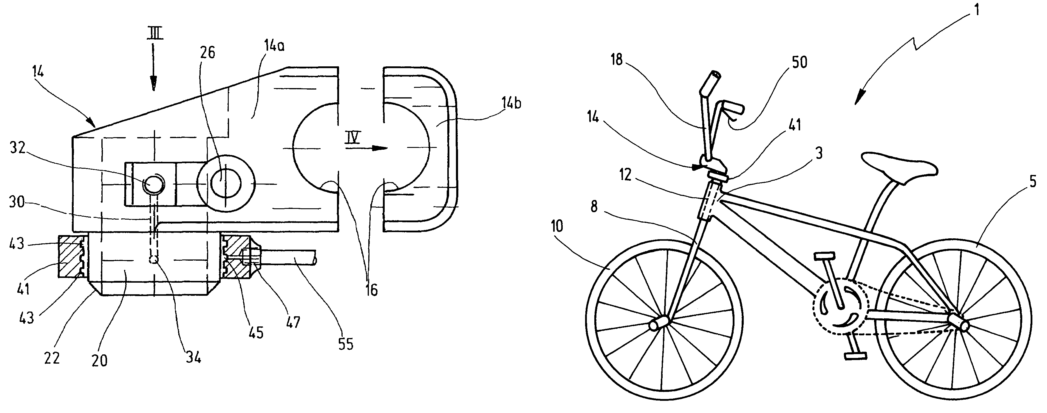
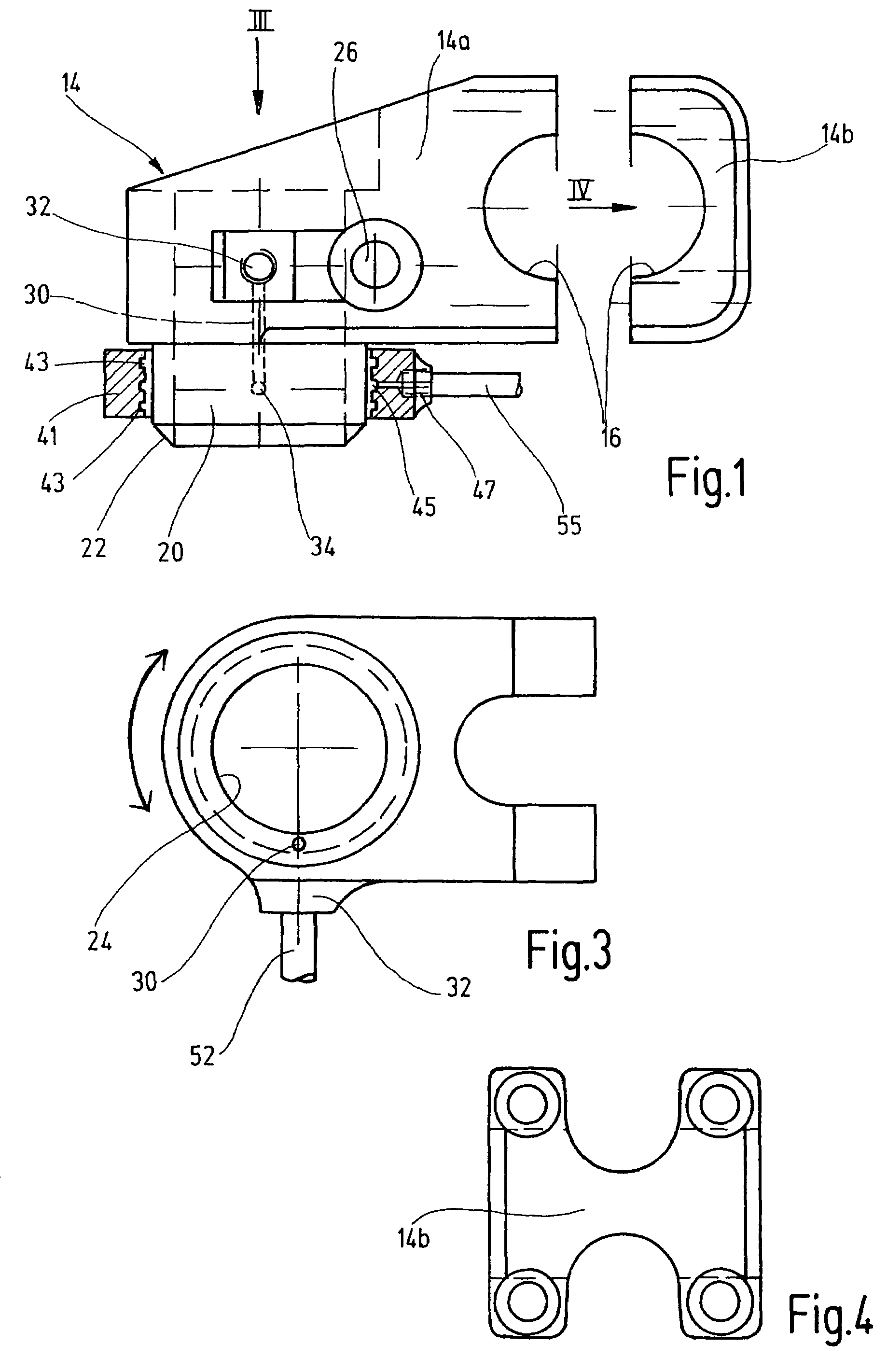
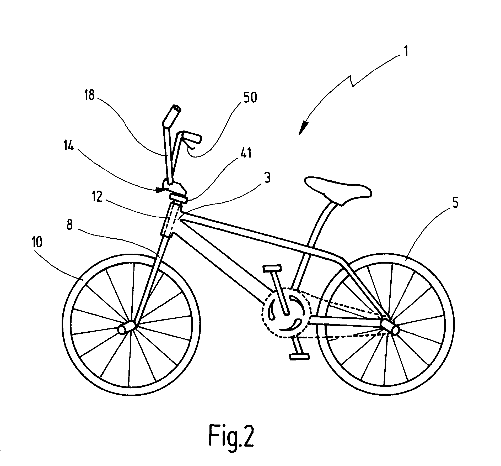
[0013]Bicycle 1 has a frame 3 that supports rear wheel 5 at the rear of bicycle 1. The upper terminus of frame 3 bears a fork 8 such that it can rotate. Fork 8 bears the front wheel 10 of bicycle 1 on its lower end. Handle stem 14 is firmly attached to fork shaft 12, which forms the upper end of fork 8. Handle stem 14 consists of a body 14a and a lid 14b, which may be screwed into the body, which by means of half-cylindrical recesses in each form a receptacle for a horizontal handle bar receptacle 16 that surrounds the handlebar 18 of bicycle 1. The normal position of handle stem 14 on bicycle 1 determines the directional parameters used below.

[0014]The underside of handle stem 14 has a cylindrical bushing 20 that extends below body 14a and that has a chamfered edge 22 at 45° on its free end. Bushing 20 is centrally traversed by a vertical shaft receptacle 24, which extends into body 14a and which is open on the upper side of handle stem 14. Fork shaft 12 is inserted into the traver...


PUM


Abstract

In a rotor system, in particular for a bicycle (1), on which a frame (3) bears a fork (8) for the front wheel (10), and a handle bar (18) is connected to the fork (8) by means of a handle stem (14) on a fork shaft (12) of the fork (8), with a first line (52), for a fluid, associated with the handle bar (14), with a second line (55), for a fluid, associated with the frame (3), and a rotor that contains two components (14, 41) that can rotate relative to each other without limits and that, by intimate contact against each other, create a closed fluid connection between the first line (52) attached to one component (14) and the second line (55) attached to the second component (41) in order to transmit the actuation of an actuation mechanism (50) associated with the handle bar (18), the handle stem (14) is one of the two components (14, 41) that can rotate relative to each other without limits and contains at least one chamber (30) included in the fluid connection between the two lines (52, 55).

Description

TECHNICAL FIELD[0001]The present invention concerns a rotor system, such as for a bicycle, on which the handle bar is connected to a fork for the front wheel, where fork is attached to frame, by means of a handle stem on a fork shaft, with a first line for a fluid associated with the handle bar, with a second line for a fluid associated with frame and a rotor that contains two components that can rotate relative to each other without limits and that, by intimate contact against each other, create a closed fluid connection between the first line attached to one component and the second line attached to the second component in order to transmit the actuation of an actuation mechanism associated with the handle bar.BACKGROUND OF THE INVENTION[0002]DE 297 08 975 U1 publicizes a rotor system of the type described above, which permits steering movements and rotation of the front wheel of more than 180° without damage to the hydraulic brake system. To do so, a rotor is attached to the fork...

Claims


Application Information

Patent Timeline
Patent Type & Authority Patents(United States)
IPC IPC(8): B62K19/18
CPCB62K21/12B60T11/046
Inventor GORING, THOMAS
Owner GORING WOLFGANG
Why Eureka
Try Eureka