Liquid ejection head, manufacturing method thereof, and image forming apparatus

a technology of liquid ejection and manufacturing method, which is applied in the direction of printing, inking apparatus, etc., can solve the problems of difficult to achieve density increase, difficult to form deep electrodes and increase the size of the head, and the connection is likely to become unstable, so as to improve productivity and precision, the effect of increasing the stability of the connection

Inactive Publication Date: 2009-11-10
FUJIFILM CORP
View PDF14 Cites 33 Cited by
  • Summary
  • Abstract
  • Description
  • Claims
  • Application Information

AI Technical Summary

Benefits of technology

[0014]The present invention has been contrived in consideration of these circumstances, and it is an object thereof to provide a liquid ejection head, a liquid ejection head manufacturing method, and an image forming apparatus in which a connection structure for a large number of electric wires can be formed efficiently, enabling improvements in productivity and precision, and increased connection stability.

Problems solved by technology

However, in the apparatus described in Japanese Patent Application Publication No. 2000-289201, for example, a structure in which an aluminum plug passes through laminated layers is employed, but since the head is formed by silicon photoetching, it is difficult to form deep electrodes and increase the size of the head.
With this constitution, however, it is difficult to achieve an increase in density, and the connections are likely to become unstable.
In the apparatus described in Japanese Patent Application Publication No. 2003-136721, it is difficult to form narrow, deep wires due to the disclosed wiring pattern, wire bonding connection, and method of extracting electrodes using thin plates.

Method used


Image

  • Liquid ejection head, manufacturing method thereof, and image forming apparatus
  • Liquid ejection head, manufacturing method thereof, and image forming apparatus
  • Liquid ejection head, manufacturing method thereof, and image forming apparatus

Examples


second embodiment

[0123]Next, the present invention will be described.

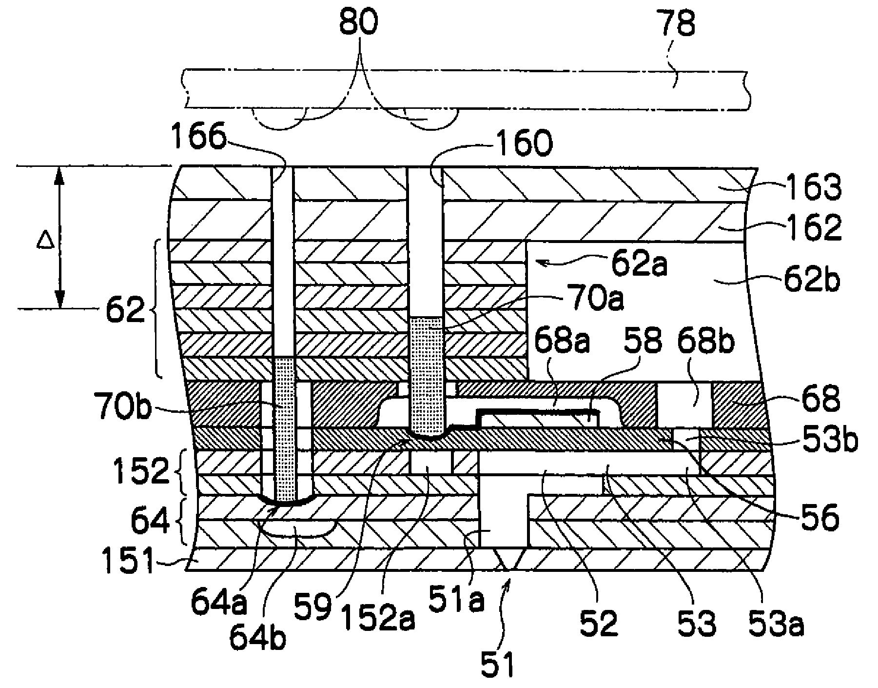
[0124]FIG. 13 is an enlarged sectional view showing a part of a print head 250 according to the second embodiment.

[0125]As shown in FIG. 13, in the print head 250 of this embodiment, the upper surface of a pressure chamber 252 which communicates with a nozzle 251 is constituted by a diaphragm 256, and a piezoelectric element 258 is formed on the upper side of the diaphragm 256. An individual electrode 257 which drives the piezoelectric element 258 is formed on the upper surface of the piezoelectric element 258, and a common liquid chamber 255 which supplies ink to the pressure chamber 252 is formed on the upper side of the diaphragm 256.

[0126]An ink supply port 253 is formed in the corner portion of the pressure chamber 252 on the opposite side to the side which communicates with the nozzle 251, and an ink supply passage 253a extends horizontally from the ink supply port 253. The ink supply passage 253a then passes through an openi...

third embodiment

[0144]Next, the present invention will be described.

[0145]In the second embodiment described above, the columnar electric wires (electric column 260, sensor column 264) pass directly through the common liquid chamber 255 as shown in FIG. 13, but in the third embodiment, partition walls which divide the common liquid chamber into a plurality of tributaries are formed by a laminated layer substrate, whereupon metal strings are passed through the partition walls and then cut to form similar columnar electric wires. Since the electric wires are formed in the partition walls of the laminated common liquid chamber in this embodiment, the strength of the wires can be improved.

[0146]FIG. 16 is an enlarged projected plan view showing a part of a print head 350 according to this embodiment.

[0147]The print head 350 of this embodiment is formed by laminating together a large number of various types of plate materials.

[0148]As shown in FIG. 16, in the print head 350, parallelogram-form pressure ...


PUM


Abstract

The liquid discharge head comprises: a plurality of ejection ports which eject liquid; a plurality of pressure chambers which communicate respectively with the plurality of ejection ports; a plurality of piezoelectric elements which deform the plurality of pressure chambers respectively and are provided on a side of the pressure chambers opposite to a side on which the ejection ports are formed; a common liquid chamber which supplies the liquid to the plurality of pressure chambers and is formed on a side of the piezoelectric element opposite to the pressure chambers; and a plurality of electric wires which stand upright from and substantially perpendicular to a surface on which the piezoelectric elements are mounted, the electric wires passing through a partition wall of the common liquid chamber and being electrically connected to the piezoelectric elements, the electric wires being formed by inserting wiring material for forming the electric wires into holes provided in the partition wall of the common liquid chamber.

Description

BACKGROUND OF THE INVENTION[0001]1. Field of the Invention[0002]The present invention relates to a liquid ejection head, a manufacturing method thereof, and an image forming apparatus, and more particularly to a technique for connecting electric wires provided at a high density in a liquid ejection head.[0003]2. Description of the Related Art[0004]An inkjet printer (inkjet recording apparatus) having an inkjet head (liquid ejection head) in which a large number of nozzles (ejection ports) are arranged is known as an image forming apparatus. This inkjet printer records an image on a recording medium by depositing ink on the recording medium from the nozzles while moving the inkjet head relative to the recording medium.[0005]In this type of inkjet printer, ink is supplied from an ink tank to a pressure chamber through an ink supply passage. A piezoelectric element is then driven by applying to the piezoelectric element an electric signal corresponding to image data, whereby a diaphrag...

Claims


Application Information

Patent Timeline
Patent Type & Authority Patents(United States)
IPC IPC(8): B41J2/045B41J2/14
CPCB41J2/14233B41J2002/14459B41J2202/21B41J2202/18B41J2202/20B41J2002/14491
Inventor HORI, HISAMITSU
Owner FUJIFILM CORP
Why Eureka
Try Eureka