Bone anchor suture-loading system, method and apparatus

a technology of suture-loading system and bone anchor, which is applied in the direction of prosthesis, ligaments, surgical forceps, etc., can solve the problems of pain and disability, inability to elevate and rotate the arm, and patient discomfort, and achieves a relatively long recovery tim

Inactive Publication Date: 2009-11-10
ARTHROCARE
View PDF419 Cites 49 Cited by
  • Summary
  • Abstract
  • Description
  • Claims
  • Application Information

AI Technical Summary

Problems solved by technology

Connective tissue such as ligaments and tendons can tear and detach from the bone and muscle to cause pain and disability.
One such tissue is the acetabular labrum in the shoulder which, if torn from its associated bone or muscle, will cause pain and inability to elevate and rotate the arm.
As will be appreciated, because the open procedure detaches the muscle and abrades the bone, the patient may experience discomfort and a relatively long recovery time.
In one arthroscopic procedure, rather than using transosseous tunnels to thread the suture through the bone, which is difficult to achieve arthroscopically, the tissue is connected to the bone by attaching one end of the suture to the tissue, securing the other end of the suture in a bone anchor, and embedding the anchor in the bone at the appropriate location thereby reattaching the tissue to the bone.
Although arthroscopic procedures are less invasive than open procedures, an arthroscopic procedure is not always the procedure used.
Also, arthroscopic suturing of the tissue is clumsy and time consuming and only the simplest stitch patterns can be utilized.
Additionally, tying a suture knot arthroscopically is challenging because it is difficult to judge the tightness of the suture.
Also, the tension on the suture is not easily adjustable arthroscopically once the knot is formed.
Further, in arthroscopic suturing, the knot required to tie the tissue may end up on top of the tissue in the form of a knot bundle, which is undesirable because of the potential for postoperative irritation when the muscle is exercised.

Method used


Image

  • Bone anchor suture-loading system, method and apparatus
  • Bone anchor suture-loading system, method and apparatus
  • Bone anchor suture-loading system, method and apparatus

Examples


Embodiment Construction

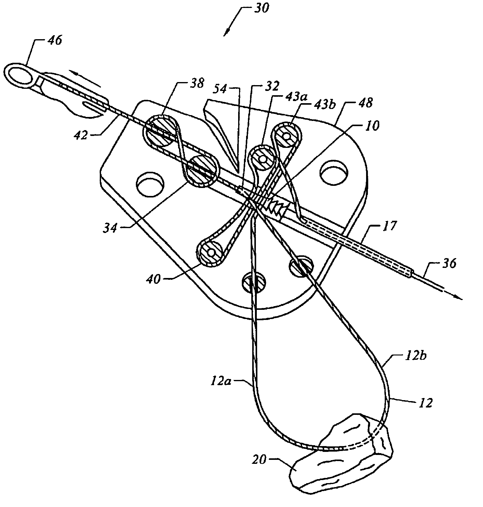
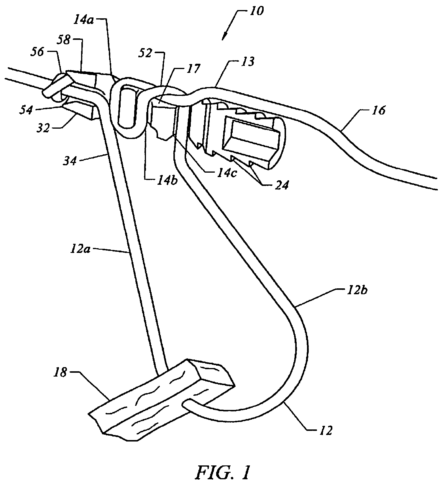
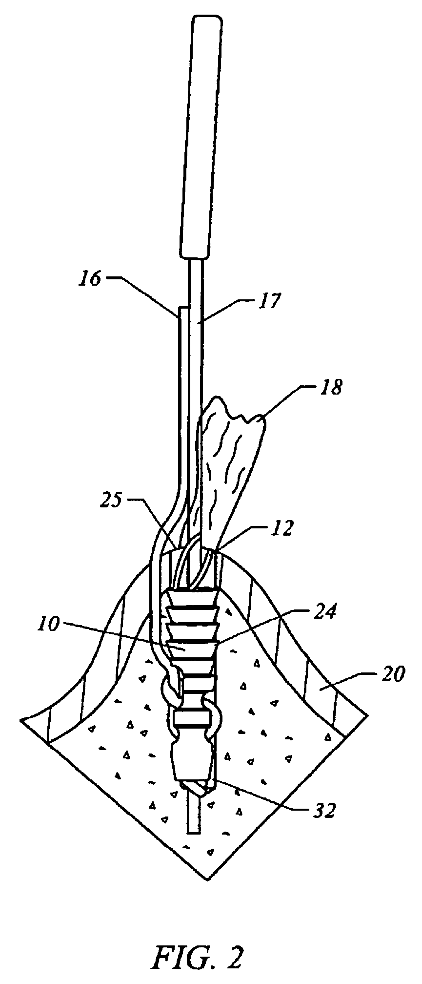
[0026]The present suture-loading system, method and apparatus are illustrated in FIGS. 1-9. In particular, an embodiment of a bone anchor loaded with a suture in accordance with the present method and system is illustrated in FIG. 5. A cross-section of the loaded anchor is illustrated in FIG. 1. The use of the loaded anchor to reattach tissue to the bone is illustrated in FIG. 2. Snare-wires attached to the suture and loaded into trackways to pull and guide the suture through the loader are illustrated in FIGS. 3, 4, 6 and 7. Algorithms of methods of loading the suture on to the anchor, and for embedding the tissue in a bone are illustrated in FIGS. 8-9.

[0027]With reference to FIGS. 1-7, the present bone anchor suture-loading system (30) comprises several components that cooperate to load and cinch the suture to the anchor. The components include: (i) a bone anchor (10) through which holes are formed to thread, knot and cinch the suture to the anchor; (ii) embedding structural featu...


PUM


Abstract

A suture-loading system, method and apparatus for loading a suture onto a bone anchor, the system comprising: a bone anchor comprising a suture leg-anchoring structure and a plurality of body holes on the anchor; a suture comprising a standing end portion and a working end portion; a standing end trackway to guide the standing end portion of the suture through the suture leg-anchoring structure; and a working end trackway to guide the working end portion of the suture through the body holes in the anchor.

Description

FIELD OF INVENTION[0001]This invention pertains to a bone anchor suture-loading system, in particular a system, method and apparatus for automatically threading, knotting and trimming a suture onto a bone anchor, and the use thereof.BACKGROUND[0002]Connective tissue such as ligaments and tendons can tear and detach from the bone and muscle to cause pain and disability. One such tissue is the acetabular labrum in the shoulder which, if torn from its associated bone or muscle, will cause pain and inability to elevate and rotate the arm. Complete separation of the tissue from the bone or muscle can occur if the body is subjected to gross trauma, but the separation can also start from a small lesion on the tissue, the bone or muscle due to aging and other factors.[0003]A detached connective tissue can surgically be reattached to the bone and muscle by an “open” procedure that involves making an incision into the body and reconnecting tissue to the bone and muscle. In one such procedure,...

Claims


Application Information

Patent Timeline
Patent Type & Authority Patents(United States)
IPC IPC(8): A61B17/04A61B17/84D03J3/00
CPCA61B17/0401A61B17/0487A61B17/06123A61B2017/2911A61B2017/0459A61B2017/0477A61B2017/0496A61B2017/0458
Inventor WHITE, GEORGE W.VIJAY, FRANCIS
Owner ARTHROCARE
Why Eureka
Try Eureka