Monorail system

a monorail and rail technology, applied in the field of spinal fusion surgery, can solve the problems of painful pressure on the nerve roots, back and radicular pain, and joints are vulnerable to degenerative spinal disorders

Active Publication Date: 2009-11-10
K2M
View PDF25 Cites 60 Cited by
  • Summary
  • Abstract
  • Description
  • Claims
  • Application Information

AI Technical Summary

Benefits of technology

[0014]Systems of this invention provide improved methods of performing a spinal fusion procedure. A monorail instrument according to this invention protects the medial neural structures, provides a sliding platform for additional instrumentation and allows controlled delivery of various instruments for disc preparation and implant insertion. The monorail system of this invention may be adapted for use with each of the PLIF, TLIF, ALIF and extreme lateral (direct lateral) procedures.

Problems solved by technology

These joints are vulnerable to degenerative spinal disorders.
Degenerative disc disease is typically caused by a loss of disc space height, leading to a narrowing of the neural foramen and subsequent neural compression, and causing back and radicular pain.
This movement of the vertebral body narrows the foramen and results in painful pressure on the nerve roots.
The instruments used in current procedures include design limitations that fail to address the challenges of the neural anatomy or require numerous instruments and steps that add significant time to the surgical procedure.
Delivery of an interbody device requires a large amount of bone resection and neural retraction.
Removal of the lamina and facet joint, which may be necessary in order to insert the implant, can potentially destabilize the motion segment.
Destabilization of the motion segment can interfere with compression of the interbody device, especially in a “stand alone” situation in which additional hardware is not utilized.
Furthermore, existing methods of introducing interbody implants into the disc space, the freehand method and the controlled method, include disadvantages.
First, existing surgical techniques in which an implant is inserted into the disc space freehand (without controlled access) and impacted into proper position present dangers to delicate neural structures.
Each time an instrument is introduced or removed from the surgical site, there is a chance that delicate structures, such as the spinal cord or nerve roots, could be compromised, potentially causing severe damage.
Additionally, maintaining constant distraction is a challenge, as instruments are passed by the neural structures “freehand.” Moreover, if a distractor is placed in the contralateral side of implantation, it does not always address the distraction needs of the operative side.
In existing “controlled” procedures, the instruments used to provide protected access to the disc space often occupy an excessive amount of the disc space.
This smaller implant does not restore proper disc space height and therefore the stability of the fusion is compromised.
Furthermore, these instruments require much more bony resection in order to be placed correctly, thus further destabilizing the spine.
This design limits visualization and neural retraction.
In addition, the design introduces a significant amount of lateralization to the placement of the implants for PLIF procedures: the implants are spaced farther apart from one another and must be implanted with a significant amount of space between them.
Further, this delivery design has poor anatomical fit, as it creates a dead space between the external wall of the retractor and the load bearing surface of the implant.

Method used


Image

  • Monorail system
  • Monorail system
  • Monorail system

Examples


Embodiment Construction

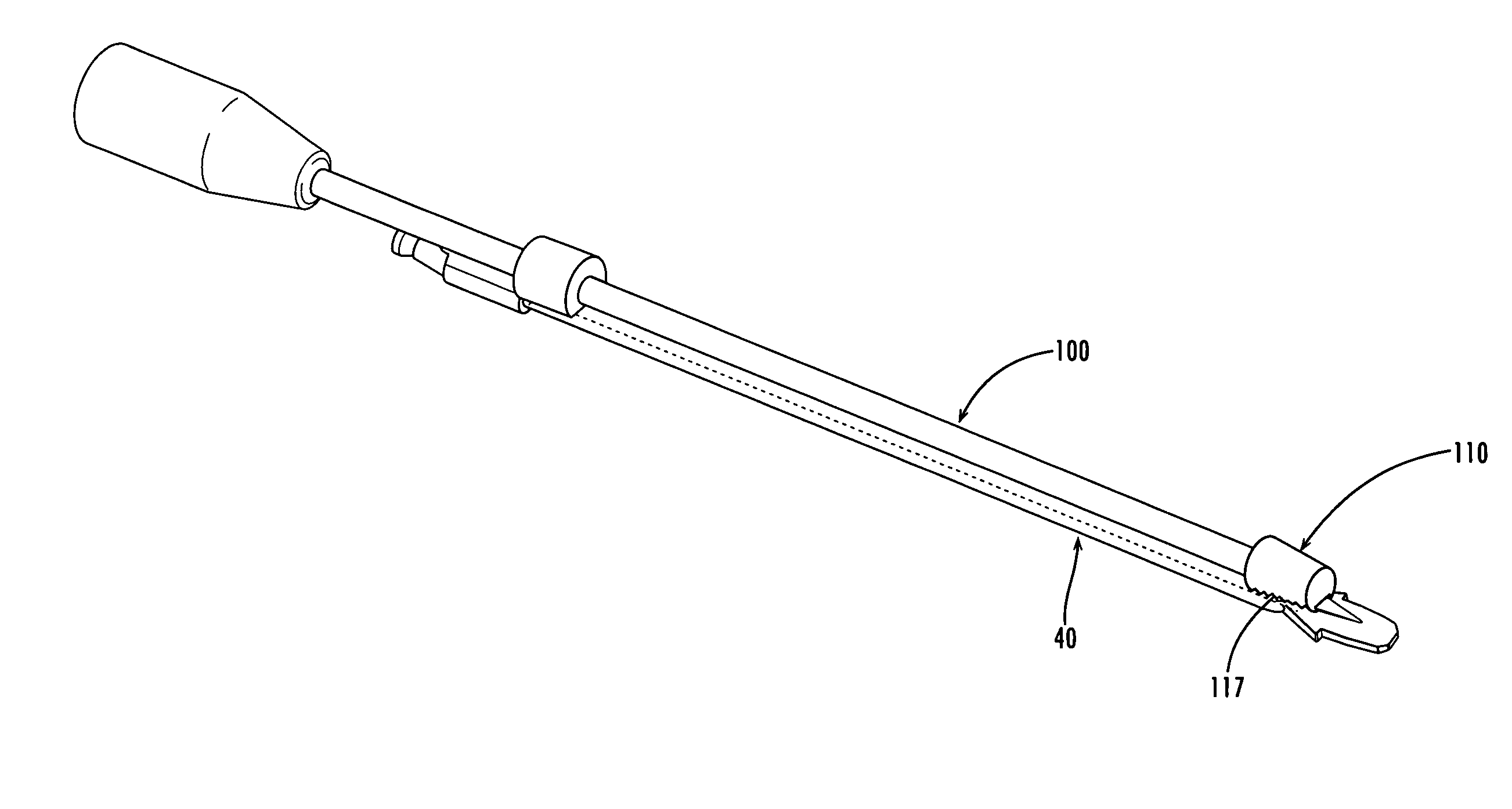
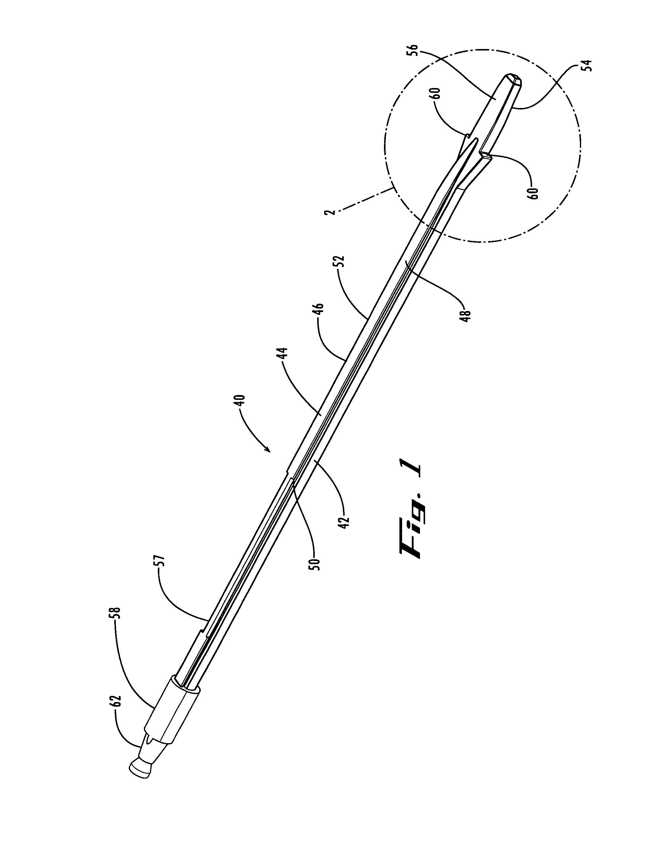
[0033]One system of this invention provides an improved method of performing a spinal fusion procedure. Generally, the system of this invention includes a tool having a monorail on one side. The instrument includes a monorail on its lateral side that accommodates various instruments utilized to prepare the disc space. For example, additional instruments such as a chisel, rasp and implant may be designed with a channel corresponding to the monorail, so that the instruments are joined to the distractor for guided and controlled insertion into the disc space. In one embodiment, the monorail instrument is a distractor, which may be inserted into the disc space and rotated to properly distract the disc space.

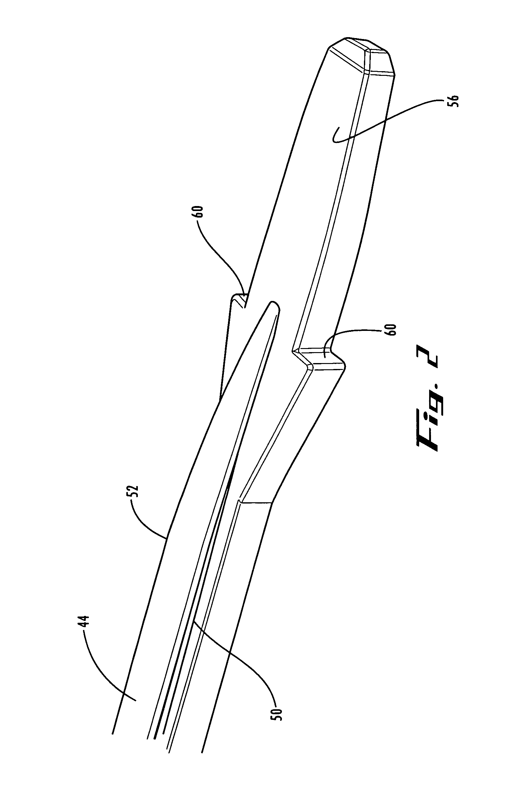
[0034]As shown in FIGS. 1-4, the monorail instrument is a distractor 40, which includes a rod 42 having a monorail 44 on its lateral side 46. In the embodiment shown in the drawings, monorail 44 includes flat top portion 48 and angled sides 50, 52 (also shown in FIG. 9). Leading end ...


PUM


Abstract

Systems providing improved methods of performing a spinal fusion procedure and including a monorail instrument that protects the medial neural structures, includes a sliding platform for additional instrumentation and allows controlled delivery of various instruments for disc preparation and implant insertion. The monorail instrument engages other instruments, including various instruments utilized to prepare the disc space as well as spinal fusion implants, for guided and controlled insertion into the disc space. The monorail instrument may be a distractor, and may include flutes for preparation of the disc space.

Description

FIELD OF THE INVENTION[0001]This invention relates generally to spinal fusion surgery and, in particular, to a system for safely and effectively delivering instruments and an implant during a spinal fusion procedure.BACKGROUND[0002]The spinal column is a flexible column formed from a linear series of vertebral bones separated by intervertebral discs. These discs reduce friction between adjacent vertebrae and absorb compression forces applied to the spinal column. A vertebra includes an anterior body and a posterior arch that surrounds the spinal cord. Spinal nerves extend from each side of the spinal cord and exit the column at the vertebral foramen, which is formed by the posterior arch. Articular processes, including the superior articular process and the inferior articular process, are small flat projections on the surfaces of the arches.[0003]There are four facet joints associated with each vertebrae, and these joints interlock with adjacent vertebrae. In this manner, facets on ...

Claims


Application Information

Patent Timeline
Patent Type & Authority Patents(United States)
IPC IPC(8): A61F2/44
CPCA61B17/025A61F2/4611A61F2250/0097A61B17/1671A61B17/1735A61B17/1757A61B2017/0256A61F2/446A61F2002/30611A61F2002/30617A61F2002/30785A61F2002/30841A61F2002/4475A61F2002/448A61F2002/4627A61F2002/4629A61F2250/0063A61B17/1604A61F2002/30604A61F2002/30593
Inventor FLICKINGER, ERICSMITHWECK, TOM
Owner K2M
Why Eureka
Try Eureka