Optical disc drive

a technology of optical disc drives and optical discs, applied in the direction of data recording, disposition/mounting of heads, instruments, etc., can solve the problem of requiring a large space for mounting, and achieve the effect of high spacing efficiency

Inactive Publication Date: 2009-11-10
HITACHI LTD
View PDF10 Cites 3 Cited by
  • Summary
  • Abstract
  • Description
  • Claims
  • Application Information

AI Technical Summary

Benefits of technology

[0010]In accordance with the invention, an actuator for optical disc drives can be realized in which a focusing operation and a tracking operation can be performed with a pair of permanent magnets. Thus, an actuator for optical disc drives that offers high spacing efficiency and that is inexpensive can be realized. Further, the use of such actuator makes it possible to realize an optical disc drive that is small-sized and inexpensive.

Problems solved by technology

However, the actuator disclosed in JP Patent Publication (Kohyo) No. 2003-500787 A requires two sets of magnet assemblies, a tracking magnet assembly and a focusing magnet assembly, thus requiring a large space for the mounting thereof.

Method used


Image

  • Optical disc drive
  • Optical disc drive
  • Optical disc drive

Examples


embodiment 1

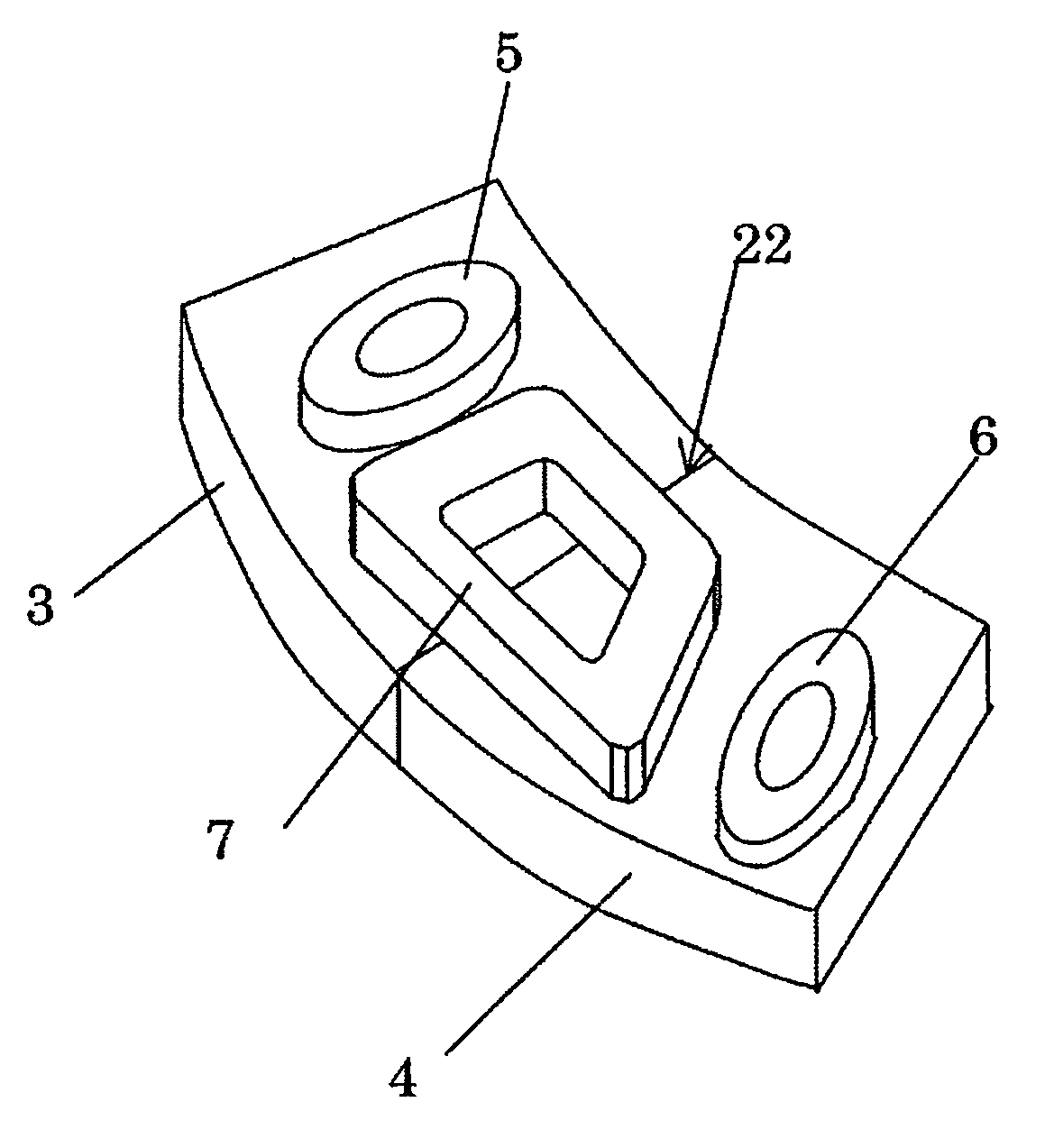
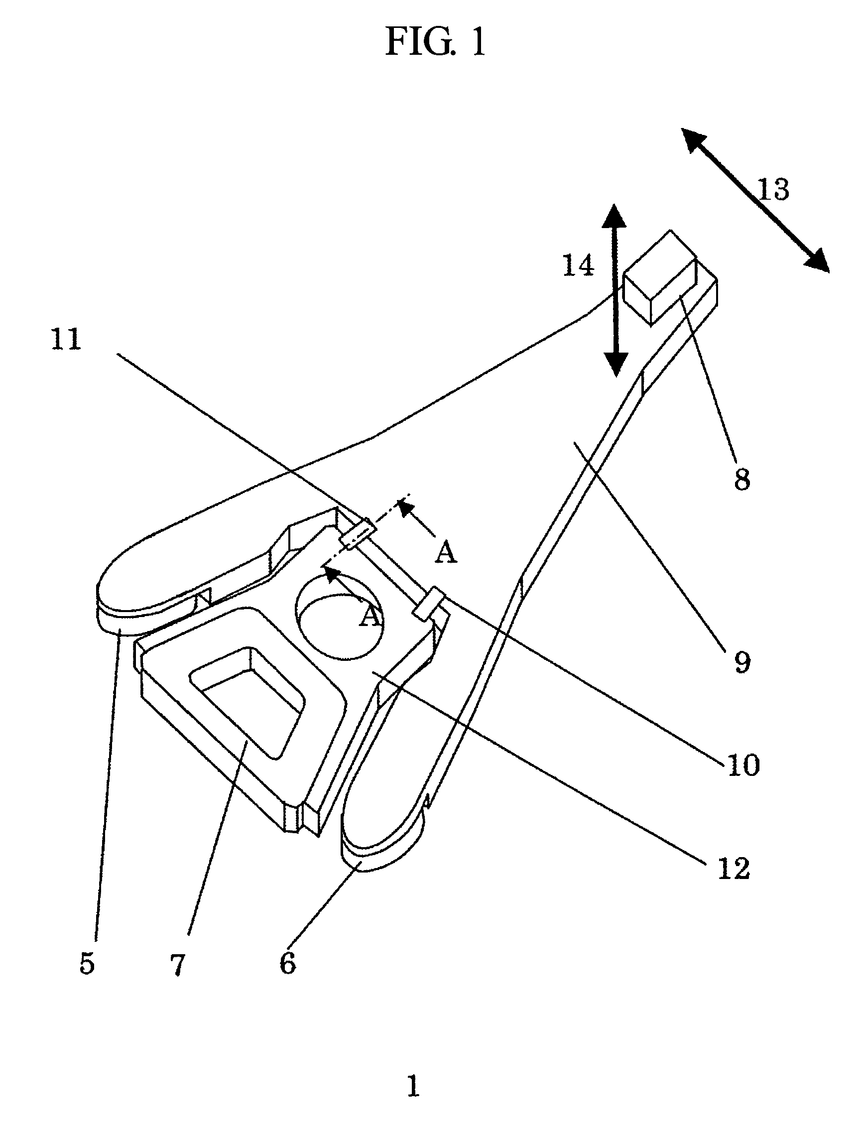
[0022]FIG. 1 shows a perspective view of an actuator moving part 1 according to Embodiment 1 of the invention.

[0023]An optical pickup 8 for the recording and reproduction or for the reproduction of information is joined to an arm 9.

[0024]The arm 9 carries focusing coils 5 and 6 and is connected to a part 12 via two hinges 10 and 11. The part 12 is connected to a swingable pivot bearing unit. The hinges 10 and 11 allow the arm 9 to be moved together with the part 12, which is fixed to the swingable pivot bearing unit in the tracking direction 13 of the optical pickup 8. The hinges 10 and 11 also allow the arm 9 to be moved separately from the part 12; namely, in a focusing direction 14 of the optical pickup 8. The part 12, which is fixed to the swingable pivot bearing unit, carries a tracking coil 7.

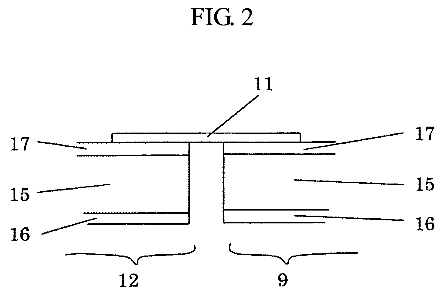
[0025]FIG. 2 shows an A-A cross section of the actuator moving part shown in FIG. 1. The arm 9 and the part 12 fixed to the swingable pivot bearing unit each have a three-layer structure ...

embodiment 2

[0035]FIG. 7 shows a cross section of a voice coil motor magnet 24 according to Embodiment 2 of the invention.

[0036]The voice coil motor magnet 24 includes, in addition to the pair of permanent magnets as according to Embodiment 1, a second pair of permanent magnets 27 and 28. The permanent magnets 27 and 28 are each joined to the upper yoke 21 such that they are opposite the permanent magnets 3 and 4, respectively. Their directions of magnetization are the same as those of the permanent magnets 3 and 4, respectively. Namely, as described above, when the polarity of the permanent magnet 3 toward a gap 31 is S, the polarity of the permanent magnet 27 toward the gap 31 is N, such that the surface of the permanent magnet 27 joined to the upper yoke 21 is S-poled and the surface of the permanent magnet 28 joined to the upper yoke 21 is N-poled, with the surface of the permanent magnet 28 toward the gap 31 being S-poled.

[0037]In Embodiment 2, as compared with Embodiment 1, the direction ...

embodiment 3

[0038]FIG. 8 shows a perspective view of an actuator moving part 32 according to Embodiment 3 of the invention. FIG. 9 shows a C-C cross section of the actuator moving part 32 shown in FIG. 8.

[0039]The arm 9 and the part 12 fixed to a swingable pivot bearing unit of this actuator moving part 32 are each made of a so-called clad material having a laminated structure consisting of an aluminum plate 15 sandwiched by stainless steel plates 16 and 17. The hinges 38 and 39 are made by forming a stainless steel plate 17 into a desired shape.

[0040]The hinges 38 and 39 are formed by first processing the stainless steel plate 17 into a desired shape by etching, press working, or electrical discharge machining, and then masking the stainless steel plate 17 and removing desired portions of a stainless steel plate 16 and an aluminum plate 15 on the opposite side by etching or electrical discharge machining.

[0041]In the present embodiment, there is no need to join the hinges to the arm or the por...


PUM

PropertyMeasurementUnit
sizeaaaaaaaaaa
sizeaaaaaaaaaa
sizeaaaaaaaaaa

Abstract

A small-sized optical disc drive includes one voice coil motor magnet within which a tracking coil and two focusing coils are disposed such that the tracking coil straddles the two poles of permanent magnets that are adjacently disposed. The two focusing coils are disposed on either side of the tracking coil, with each of the two focusing coils being only disposed over one of the permanent magnets.

Description

BACKGROUND OF THE INVENTION[0001]1. Field of the Invention[0002]The invention relates to an optical disc drive and particularly to a swing arm-type head positioning actuator for optical disc drives.[0003]2. Background Art[0004]An example of the aforementioned type of actuator is disclosed in JP Patent Publication (Kohyo) No. 2003-500787 A.[0005]Actuators for hard disk drives and optical disc drives, which employ rotational disk (disc) information recording media, include linear actuators by which a recording / reproducing head or a reproducing head is moved linearly, and swing arm (also referred to as “rotary”) actuators by which such head is moved in a swinging manner. When it is desired that the drives be reduced in size, a swing arm actuator is employed. In optical disc drives, the actuator performs a focusing operation for maintaining a constant distance between the head and the disc surface, in addition to the operation to position the head at a desired position along the radius ...

Claims


Application Information

Patent Timeline
Patent Type & Authority Patents(United States)
IPC IPC(8): G11B7/00
CPCG11B7/08576G11B7/0935G11B7/0933G11B7/09G11B7/095G11B21/02G11B7/085
Inventor NAKAMURA, SHIGEOSHIMANO, TAKESHIHORINO, MASAYANANIWA, IRIZOPARK, NO-CHEOLYOO, JEONGHOONLEE, DONG-JUOH, JESEUNGPARK, CHUL
Owner HITACHI LTD
Why Eureka
Try Eureka