
Call admission control/session management based on N source to destination severity levels for IP networks

a call admission control and call management technology, applied in the field of control and maintenance of quality of service (qos) in telecommunications networks, can solve the problems of complex control and packet routing schemes, affecting the number of calls or sessions taking place on the network, and affecting the quality of service of the network

Inactive Publication Date: 2009-11-10
GENERAL DYNAMICS C4 SYSTEMS
View PDF6 Cites 72 Cited by
  • Summary
  • Abstract
  • Description
  • Claims
  • Application Information

AI Technical Summary

Problems solved by technology

Adding a new call to an IP network may not only cause the new call to violate QoS requirements, but may also cause deleterious effects on other calls or sessions taking place on the network.
Conventional packet switching algorithms may regulate the QoS in a non-distributed fashion, leading to complex control and packet routing schemes.
This conventional approach suffers from a number of drawbacks.
One such drawback is that the algorithm is traditionally very complex, and in many instances will need to evaluate traffic throughout the network (e.g., at each node) to control traffic entering and exiting, for example, a WAN at each of the nodes.
Thus, the calculations required for a network-wide control may be time consuming and may require a great deal of processing resources.
Additionally, the addition of new nodes to the network may be problematic as the network-wide algorithm may have to be revised and updated to satisfy the changes to the network.
Additionally, some conventional approaches may admit certain calls to a network and determine only a few seconds later that that call violates QoS requirements, which may require the network to subsequently drop the call after the call has had the opportunity to negatively impact ongoing calls or sessions on the network.

Method used


Image

  • Call admission control/session management based on N source to destination severity levels for IP networks
  • Call admission control/session management based on N source to destination severity levels for IP networks
  • Call admission control/session management based on N source to destination severity levels for IP networks

Examples


Embodiment Construction

[0033]The present disclosure will now be described more fully with reference to the Figures in which embodiments of the present invention are shown. The subject matter of this disclosure may, however, be embodied in many different forms and should not be construed as being limited to the embodiments set forth herein.

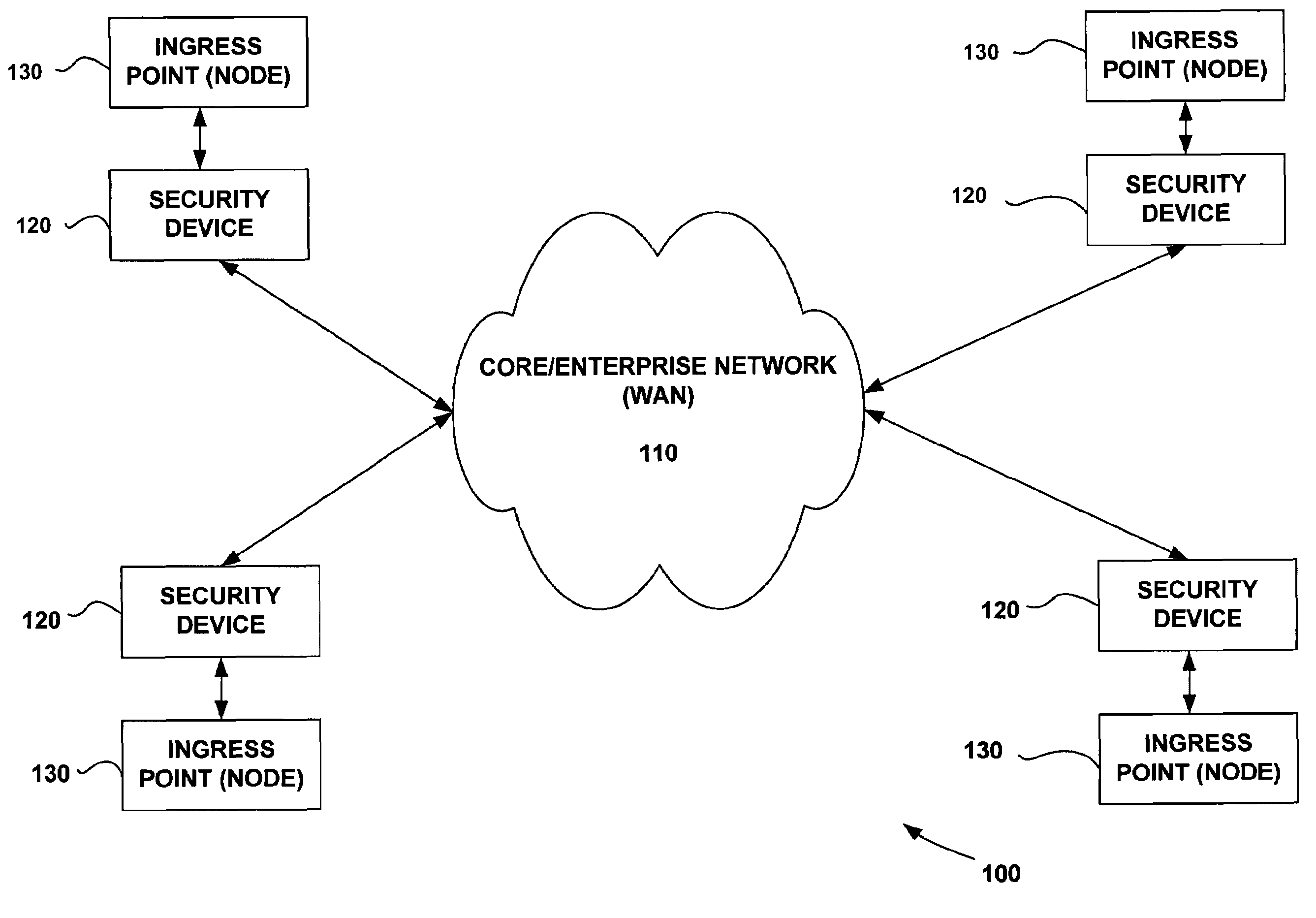
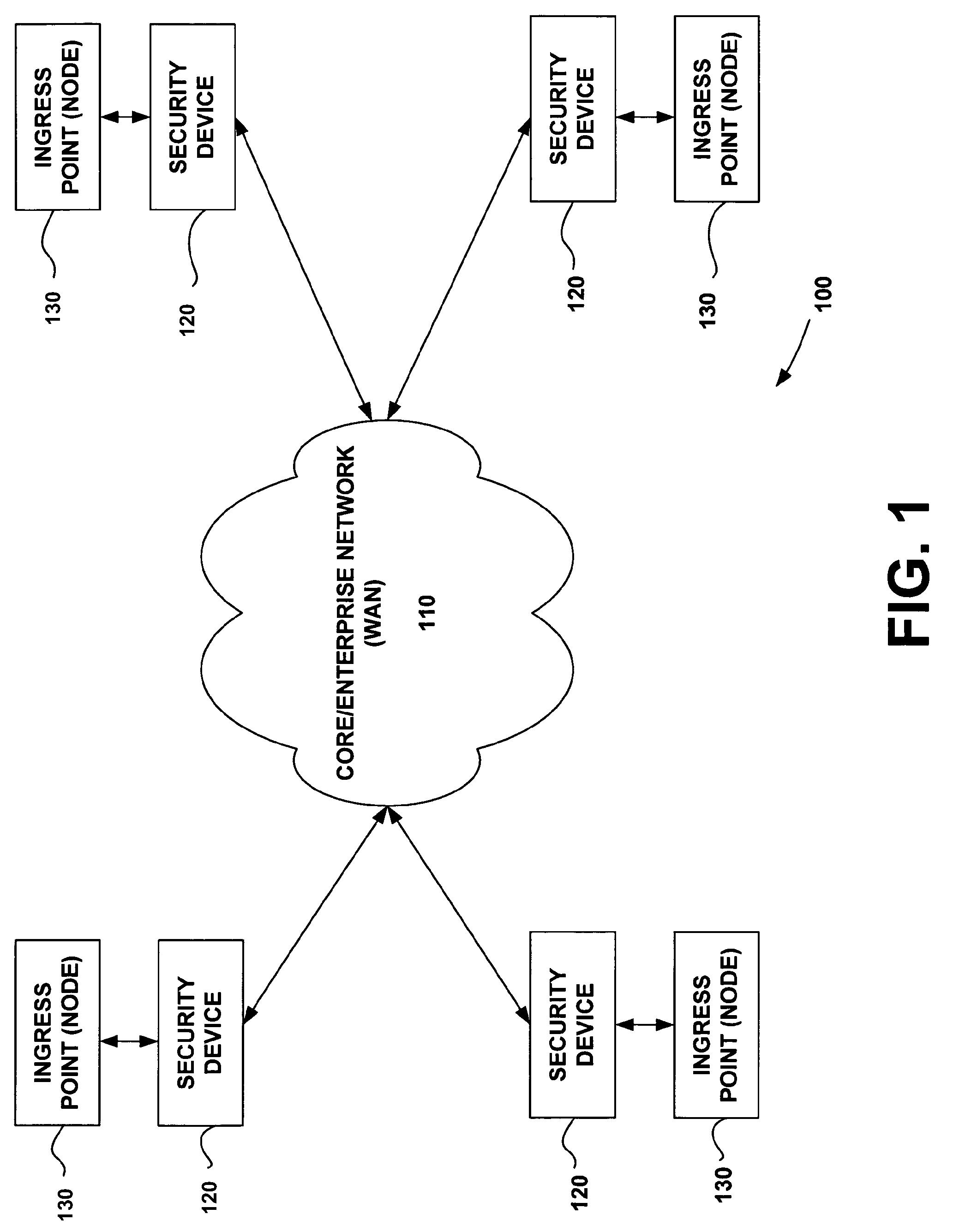
[0034]FIG. 1 shows an exemplary network topology 100 having a core (WAN) 110 and multiple LANs communicating over the WAN. An algorithm according to an aspect of the invention may reside at the ingress point node 130 of each LAN. The algorithm may also be configured to permit each LAN to block, admit, or preempt calls without requiring any QoS information exchange with the WAN 110. The absence of QoS information may be due to, for example, security requirements, which may be enforced by security devices 120 (as in military networks). Alternatively, the absence of QoS information may be because the WAN was developed by a service provider and services were sold to enterpri...


PUM


Abstract

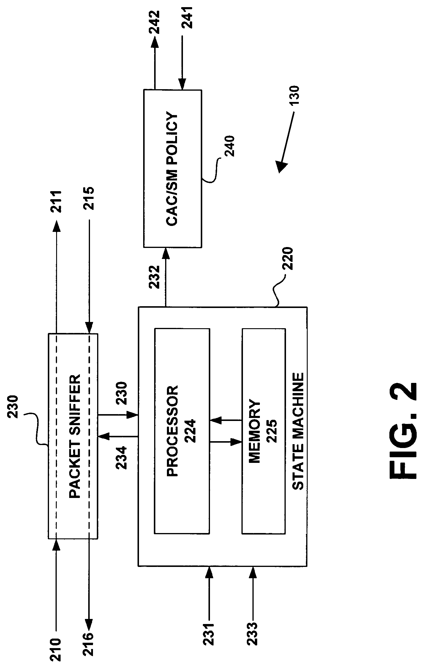
In a first aspect, an apparatus may include a first node and a second node. The first node may be configured to transmit packets of data to the second node. A first processor may be associated with the first node and a second processor may be associated with a second node. The second processor may be configured to calculate a severity level. The severity level may then be transmitted to the first node so that the first processor can determined a call admission policy (CAC / SM) policy to regulate the transmission of packets of data from the first node to the second node. In one embodiment, the number of severity levels associated with a particular network configuration may vary according to sensitivity.

Description

CROSS REFERENCE TO RELATED APPLICATIONS[0001]This application is a non-provisional application of Provisional Application Ser. No. 60 / 459,231 filed Mar. 31, 2003, entitled “Call Admission Control / Session Management Based on N Source to Destination Severity Levels for IP Networks,” which is hereby incorporated by reference in its entirety.FIELD OF THE INVENTION[0002]This invention relates generally to the control and maintenance of quality of service (QoS) in telecommunications networks. More particularly, the invention relates to the maintenance of QoS within a packet switched network using a combined call admission control / session management (CAC / SM) algorithm.BACKGROUND OF THE INVENTION[0003]Packet switched networks transmit data in packets between two or more nodes. Packets include data frames having header records that provide relevant information to the network. This header information may identify the packet to the network. Each node in a packet switched network may advance th...

Claims


Application Information

Patent Timeline
Patent Type & Authority Patents(United States)
IPC IPC(8): H04L12/26H04L12/28H04L12/56
CPCH04L12/5695H04L47/822H04L43/0852H04L47/11H04L47/15H04L47/2416H04L47/2441H04L47/245H04L47/26H04L47/283H04L47/745H04L47/801H04L47/805H04L43/0829H04L43/16H04L47/70H04L47/10H04L47/267H04L12/56H04L43/00
Inventor ELMASRY, GEORGE F.MCCANN, C. JOHN
Owner GENERAL DYNAMICS C4 SYSTEMS
Learn More