Six-bar linkage positioning mechanism

a positioning mechanism and six-bar technology, applied in the direction of mechanical control devices, instruments, packaged goods, etc., can solve the problems of inability to estimate the safety of the motion mechanism, inability to accurately control the motion path,

Inactive Publication Date: 2009-11-17
IND TECH RES INST
View PDF16 Cites 6 Cited by
  • Summary
  • Abstract
  • Description
  • Claims
  • Application Information

AI Technical Summary

Benefits of technology

[0013]The present invention has been accomplished to provide a six-bar linkage positioning mechanism that eliminates the drawbacks of the aforesaid prior art design. The six-bar linkage positioning mechanism is mounted inside a clean container, the clean container comprises a base and a cover shell covered on the base and holds a cassette on the base, which cassette has a plurality of insertion slots horizontally arranged at different elevations for carrying a plurality of workpieces in the insertion slots. The six-bar linkage positioning mechanism comprises a locating member, a four-bar linkage, and a driving module. The locating member is fixedly fastened to an inside wall of the cover shell, and the locating member having a vertically extended sliding way. The four-bar linkage comprises a first link, a second link, a third link, and a fourth link. The fourth link is fixedly fastened to the locating member. The first link and the third link are arranged in parallel and have the same length. The second link and the fourth link are arranged in parallel and have the same length. The driving module comprises a slide and a driving link. The slide is sliding along the vertically extended sliding way of the locating member. The driving link has a first end pivoted to the slide and a second end pivoted to one of the first, second and third links of the four-bar linkage. When covering the cover shell on the base from the top, the slide will be stopped at the base and be forced to slide upwards along the vertically extended sliding way, thereby causing the driving link to drive the four-bar linkage upwards and to further force the second link to push the workpieces in the insertion slots horizontally forwards.
[0014]According to the aforesaid arrangement, the locating member, the four-bar linkage and the driving module of the six-bar linkage positioning mechanism, which is comprised of six linking elements (four links of the four-bar linkage, the driving link and the driving slide) and has six rotation pairs and one sliding pair. According to Gruebler's formula, F=3(6−1)−2*7=1, therefore the whole mechanism has one degree of freedom, i.e., the second link of the four-bar linkage can be forced horizontally to push every workpiece in horizontal. Therefore, this six-bar linkage positioning mechanism pushes every wafer horizontally into position by means of contact at a point to prevent contamination due to friction and to improve moving stability of the linkage.
[0019]The six-bar linkage positioning mechanism of this embodiment has one degree of freedom for causing horizontal movement of the second link of the four-bar linkage to push every workpiece in the respective insertion slot in horizontal. Therefore, this embodiment achieves same contact at a point to prevent contamination due to friction and to improve moving stability of the linkage.

Problems solved by technology

However, because the inside space of a conventional wafer container is much greater than a wafer cassette, storage wafers may slip inside a wafer container during its transportation.
In this case, it cannot accurately control the motion path and thereby unable to estimate the safeness of the motion mechanism.
This motion causes the same problem.

Method used


Image

  • Six-bar linkage positioning mechanism
  • Six-bar linkage positioning mechanism
  • Six-bar linkage positioning mechanism

Examples


first embodiment

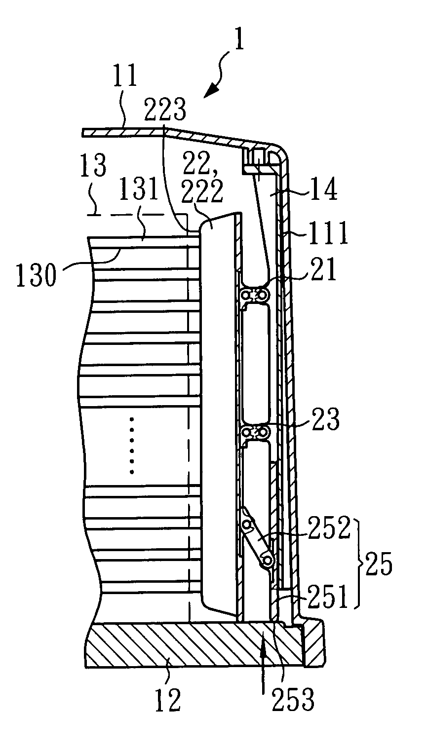
[0060]Referring to FIG. 8 through FIG. 12, a six-bar linkage positioning mechanism is shown constructed according to the present invention and mounted inside a clean container 1. The clean container 1 comprises a base 12, and a cover shell 11 covered on the base 12. The base 12 holds a cassette 13 at the top. The cassette 13 comprises a plurality of insertion slots 130 transversely (horizontally) arranged at different elevations for carrying a plurality of workpieces 131. According to this embodiment, the workpieces 131 are wafers.

[0061]Further, the aforesaid six-bar linkage positioning mechanism comprises a locating member 14, a four-bar linkage 2, and a driving module 25. The locating member 14 is fixedly fastened to an inside wall 111 of the cover shell 11 of the clean container 1. The locating member 14 has a vertically extended sliding way 141 and two mounting holes 142 respectively formed in the two distal ends of the top thereof and respectively fixedly fastened to the inside...

third embodiment

[0068]FIG. 18˜FIG. 22 show a six-bar linkage positioning mechanism constructed according to the present invention. According to this embodiment, the six-bar linkage positioning mechanism is mounted inside a clean container 5, which comprises a base 52 and a cover shell 51 covered on the base 52. The base 52 holds a cassette 53 at the top. The cassette 53 comprises a plurality of insertion slots 530 transversely (horizontally) arranged at different elevations for carrying a plurality of workpieces 531. According to this embodiment, the workpieces 531 are wafers.

[0069]According to this embodiment, the six-bar linkage positioning mechanism comprises a locating member 55, a parallel four-bar linkage 4, and a supporting link 45. The locating member 55 is fixedly fastened to an inside wall 511 of the cover shell 51 of the clean container 5. The locating member 55 has a vertically extended sliding way 551 vertically disposed on the middle, and two mounting holes 552 respectively formed in ...

fifth embodiment

[0076]FIG. 28˜FIG. 32 show a six-bar linkage positioning mechanism constructed according to the present invention. According to this embodiment, the six-bar linkage positioning mechanism comprises a first link 71, a second link 72, a third link 73, a fourth link 74, a fifth link 75, and a sixth link 76. The sixth link 76 is axially slidably slid along the first link 71. The fourth link 74 has three pivot points 741, 742 and 743 respectively pivoted to the third link 73, the fifth link 75 and the sixth link 76. The fifth link 75 is pivotally pivoted between the second link 72 and the fourth link 74.

[0077]When the sixth link 76 (the slide) is moved, it will carry the third link 73 (the retainer) to move workpieces 771 transversely (horizontally) in the cassette 77 by means of contact at a point. Therefore, the six-bar linkage positioning mechanism is constructed to have one degree of freedom so that the third link 73 can be moved transversely (horizontally) to push every workpiece 771...


PUM


Abstract

Disclosed is a six-bar linkage positioning mechanism mounted inside a clean container formed of a locating member and a four-bar linkage and a driving module which, when moved, has the slide of the driving module stopped at the base of the cleaning container and be forced to move upwards relative to a sliding way inside the locating member and to cause the driving link of the driving module to drive the four-bar linkage upwards and to further force the second link of the four-bar linkage to push workpieces in respective insertion slots in a cassette on the clean container. The six-bar linkage positioning mechanism has only one degree of freedom so that it moves workpieces horizontally in the cassette into position by means of contact at a point, preventing contamination due to friction and also improving moving stability.

Description

BACKGROUND OF THE INVENTION[0001]1. Field of the Invention[0002]The present invention relates to a six-bar linkage positioning mechanism and more particularly, to such a six-bar linkage positioning mechanism practical for use in a clean container for holding a plurality of workpieces which vertically spaced and horizontally arranged in position without producing friction.[0003]2. Description of Related Art[0004]In a semiconductor foundry, wafer cassettes are used to hold semiconductor wafers in horizontal at different elevations. A wafer cassette for this purpose has bearing flanges, defining a plurality of horizontal insertion slots at different elevations for accommodating semiconductor waters. When a wafer cassette is fully loaded with semiconductor wafers, the wafer cassette is then mounted on the base of a clean container, and then a cover shell is covered on the base to protect storage wafers against contamination.[0005]Conventionally, a wafer cassette is simply received in a ...

Claims


Application Information

Patent Timeline
Patent Type & Authority Patents(United States)
IPC IPC(8): B65D85/00
CPCH01L21/67369Y10T74/20Y10S414/136Y10S414/13
Inventor CHEN, KUAN-CHOUWU, TZONG-MING
Owner IND TECH RES INST
Why Eureka
Try Eureka