Curved sensor array apparatus and methods

Inactive Publication Date: 2009-11-17
RIEL RYAN D +2
View PDF17 Cites 24 Cited by
  • Summary
  • Abstract
  • Description
  • Claims
  • Application Information

AI Technical Summary

Benefits of technology

[0018]An object of the present invention is to provide improved curved sensor array configurations and for methods of processing the data gathered by the sensors. A first embodiment comprises singular ring of sensors that can monitor sources in a 2 dimensional plane. A sensor directly facing a target produces a m

Problems solved by technology

When the sensor array detects more than one target, deconvolvi

Method used


Image

  • Curved sensor array apparatus and methods
  • Curved sensor array apparatus and methods
  • Curved sensor array apparatus and methods

Examples


Embodiment Construction

[0046]The following acronyms are used herein:

[0047]FOR—Field of regard (for the sensor array)

[0048]FOV—Field of view (for an individual sensor)

[0049]FPA—focal plane array

[0050]IRST—Infrared search and track

[0051]PTZ—Pan, tilt, zoom

[0052]SDS—Spherical detection systems

[0053]SSC—Spherical sensor configurations

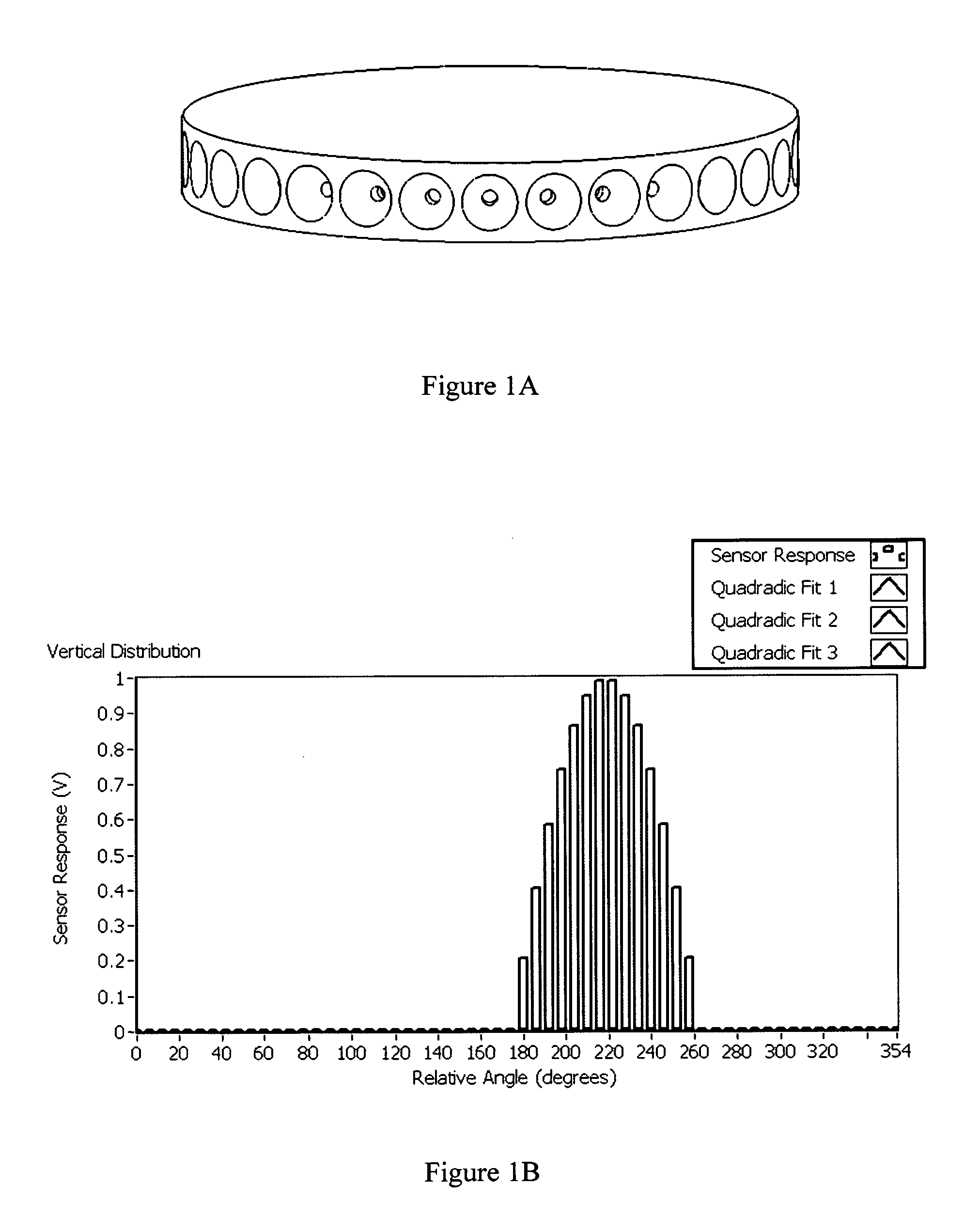
[0054]FIG. 1A is a schematic drawing illustrating a first, 2 dimensional, embodiment of the present invention. The invention provides a robust method for locating sources in 2D. The 2D prototype was designed with 30 IR sensors mounted on a 4 inch diameter ring. The sensors have a 100° FOV and are each separated angularly by 12 degrees. The sensors receive light in the 350-1150 nanometer spectral range. The sampling rate is variable up to 100 kHz and is generally set to 10 Hz for display purposes.

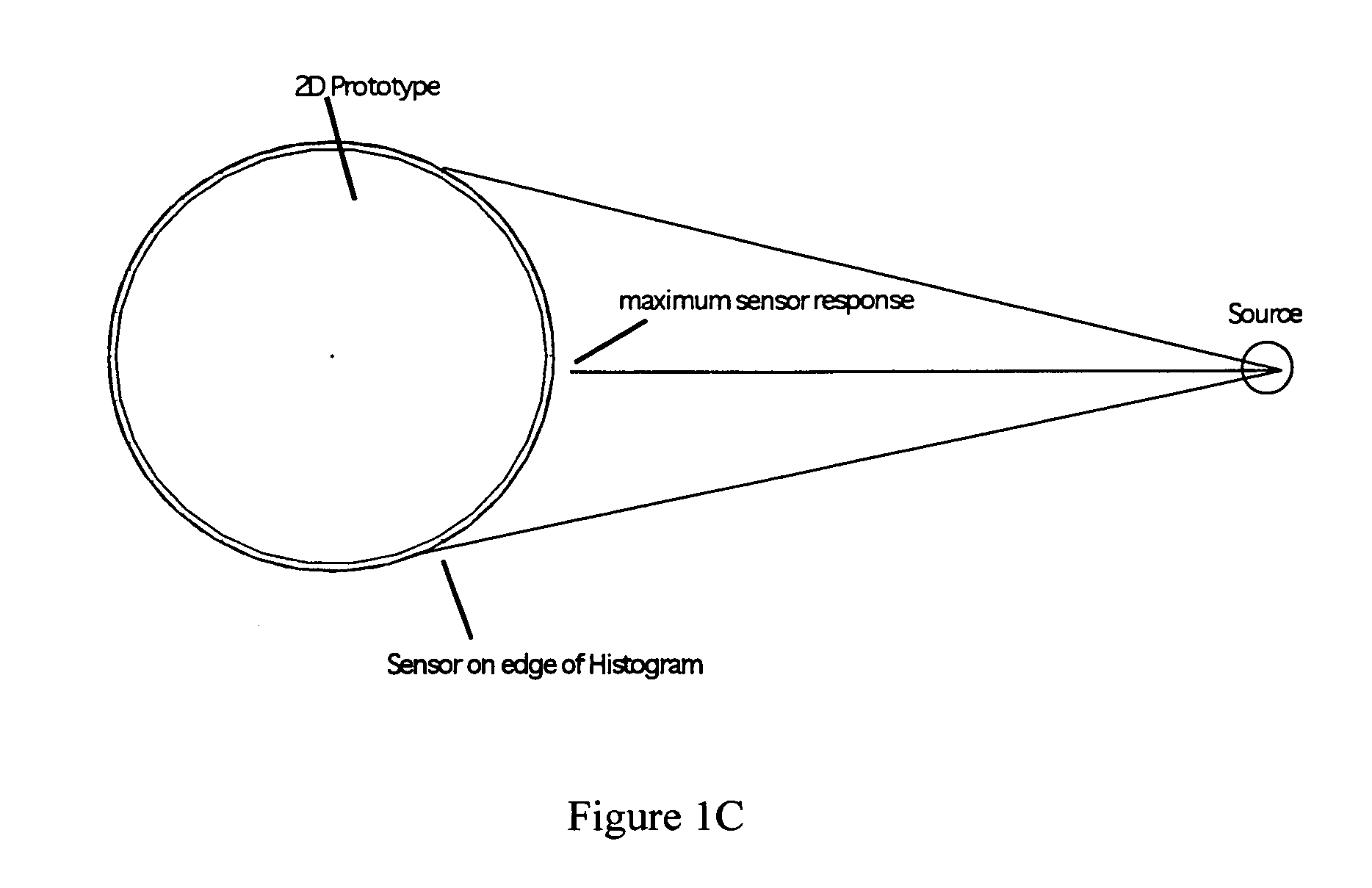
[0055]Sensors directly facing an IR source produce a maximum response from the source relative to the other sensors on the ring, as shown in FIG. 1C. As the angle of the sensor relative t...


PUM


Abstract

Curved sensor array configurations and methods of processing the data gathered by the sensors. A 2 dimensional embodiment comprises singular ring of sensors that can monitor sources in a 2 dimensional plane. A sensor directly facing a target produces a maximum response. As the angle of a sensor relative to the target increases, the response decreases. Fitting the sensor response amplitudes to a 2D Gaussian curve and calculating the peak of the curve allows a very accurate calculation of the angular direction of the target. A 3D embodiment comprises sensors distributed over the surface of a sphere in order to monitor multiple targets in any spatial orientation. Again, the sensor amplitude data is fitted to a 3D curve or surface such as a Gaussian surface. The present invention can resolve more than one target using deconvoluting techniques.

Description

[0001]This application claims the benefit of Provisional Application for Patent Ser. No. 60 / 925,512, filed Apr. 20, 2007 and Provisional Application for Patent Ser. No. 61 / 067,420, filed Feb. 28, 2008.[0002]U.S. Pat. No. 7,277,053 is incorporated herein by reference.BACKGROUND OF THE INVENTION[0003]1. Field of the Invention[0004]The present invention relates to curved sensor array apparatus and methods. In particular, the present invention relates to configurations of curved sensor arrays and methods of processing data gathered from the sensors.[0005]2. Description of the Related Art[0006]U.S. Pat. No. 7,277,053 (to a subset of the present inventors and incorporated herein by reference) teaches apparatus and methods for detecting and locating signals. That invention utilized sensors arrayed on a sphere or the like to determine the direction of a sensed signal.[0007]While the apparatus and methods of U.S. Pat. No. 7,277,053 work well in detecting targets widely spread in space, impro...

Claims


Application Information

Patent Timeline
IPC IPC(8): G01B11/14
CPCG01S3/784G01C3/00
Inventor RIEL, RYAN D.CALIHMAN, ADAM E.THOMSON, DAVID S.
Owner RIEL RYAN D
Why Eureka
Try Eureka