
Plenoptic camera

a technology of plenoptic camera and optical information, which is applied in the field of cameras, can solve the problems of inconvenient use, inconvenient use, and inability to capture a large amount of optical information in conventional cameras,

Inactive Publication Date: 2009-11-17
ADOBE SYST INC
View PDF13 Cites 180 Cited by
  • Summary
  • Abstract
  • Description
  • Claims
  • Application Information

AI Technical Summary

Benefits of technology

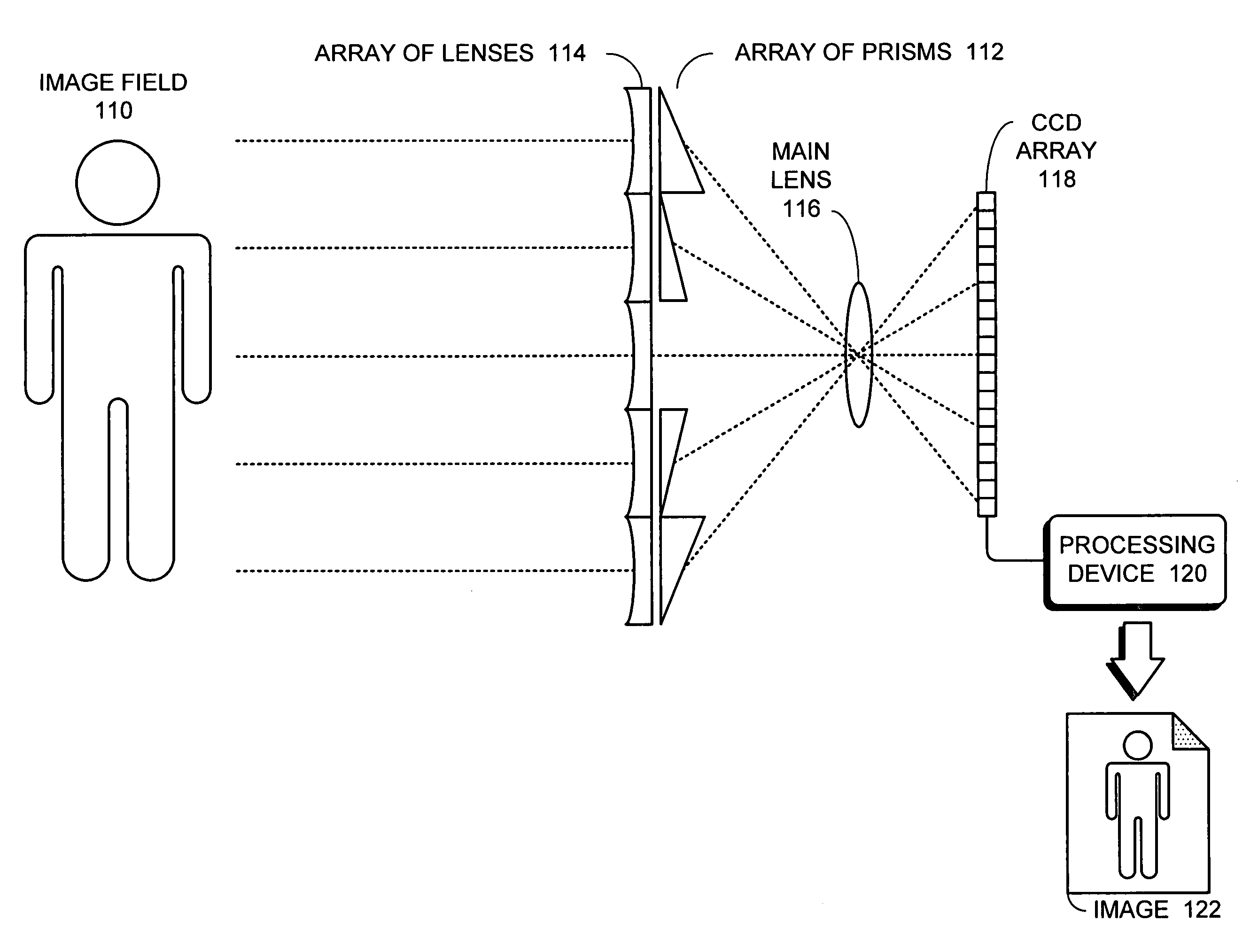
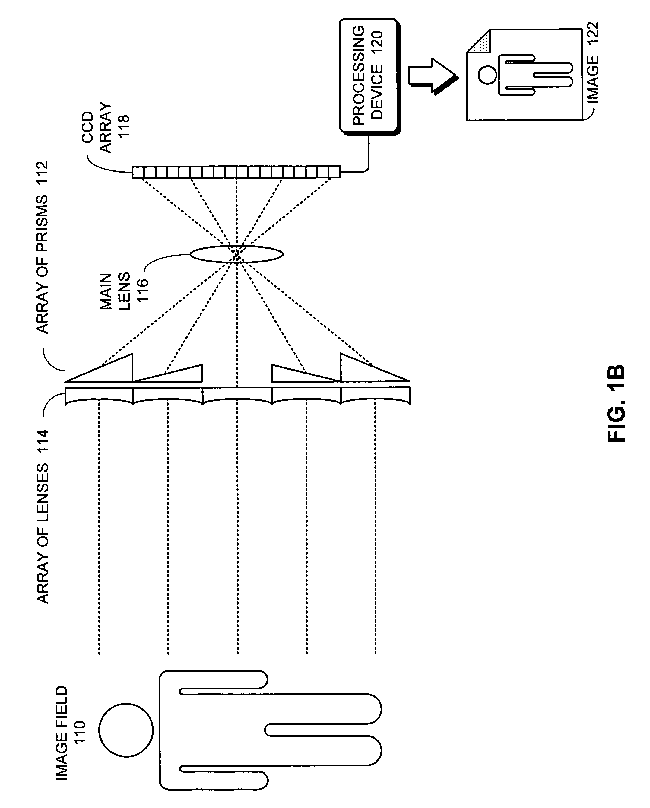
[0010]One embodiment of the present invention provides a plenoptic camera which captures information about the direction distribution of light rays entering the camera. Like a conventional camera, this plenoptic camera includes a main lens which receives light from objects in an object field and directs the received light onto an image plane of the camera. It also includes a photodetector array located at the image plane of the camera, which captures the received light to produce an image. However, unlike a conventional camera, the plenoptic camera additionally includes an array of optical elements located between the object field and the main lens. Each optical element in this array receives light from the object field from a different angle than the other optical elements in the array, and consequently directs a different view of the object field into the main lens. In this way, the photodetector array receives a different view of the object field from each optical element in the array.

Problems solved by technology

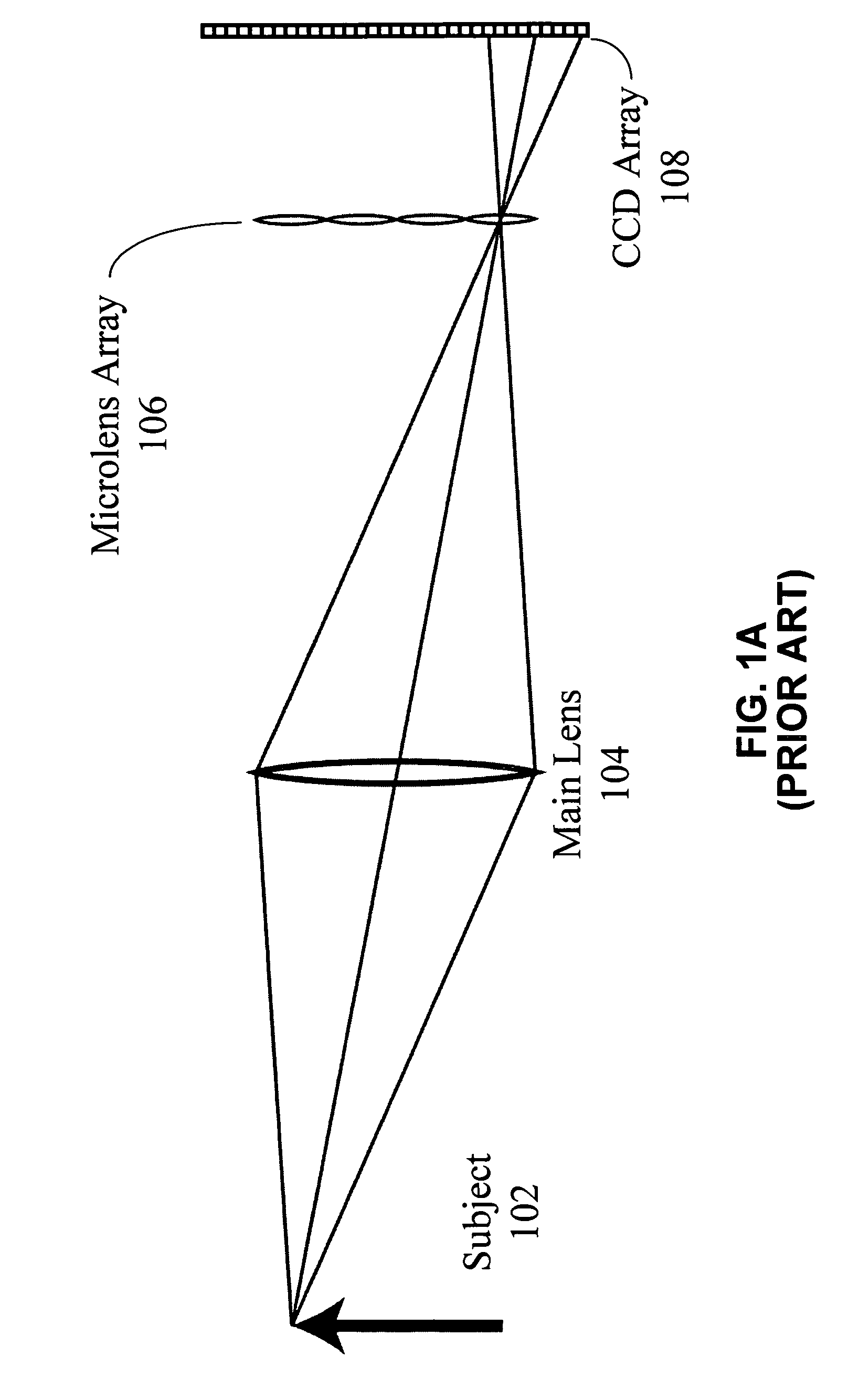
Conventional cameras fail to capture a large amount of optical information.
In particular, a conventional camera does not capture information about the location of the aperture of the light rays entering the camera.
However, this 2D image contains no information about the directional distribution of the light that strikes the photosensor.
However, only about 100 of these pixels are useful because of poor quality of edge pixels caused by a problem which is referred to as “vignetting.” These 100 pixels which comprise each macropixel make the captured data equivalent to 100 conventional images, one for each choice of the pixel inside a macropixel.
Unfortunately, an image with only 300×300 pixels has insufficient resolution for most practical uses.
Unfortunately, the prior art cannot use the border pixels of each image.
Because of this problem, the system described in [Ng05] cannot reduce the size of each microlens and the image under it.
Consequently, the number of microlenses, and hence the resolution of the image, is limited.

Method used


Image

  • Plenoptic camera
  • Plenoptic camera
  • Plenoptic camera

Examples


Embodiment Construction

[0032]The following description is presented to enable any person skilled in the art to make and use the invention, and is provided in the context of a particular application and its requirements. Various modifications to the disclosed embodiments will be readily apparent to those skilled in the art, and the general principles defined herein may be applied to other embodiments and applications without departing from the spirit and scope of the present invention. Thus, the present invention is not limited to the embodiments shown, but is to be accorded the widest scope consistent with the claims.

[0033]The data structures and code described in this detailed description are typically stored on a computer-readable storage medium, which may be any device or medium that can store code and / or data for use by a computer system. This includes, but is not limited to, magnetic and optical storage devices such as disk drives, magnetic tape, CDs (compact discs), DVDs (digital versatile discs or ...


PUM


Abstract

One embodiment of the present invention provides a plenoptic camera which captures information about the direction distribution of light rays entering the camera. Like a conventional camera, this plenoptic camera includes a main lens which receives light from objects in an object field and directs the received light onto an image plane of the camera. It also includes a photodetector array located at the image plane of the camera, which captures the received light to produce an image. However, unlike a conventional camera, the plenoptic camera additionally includes an array of optical elements located between the object field and the main lens. Each optical element in this array receives light from the object field from a different angle than the other optical elements in the array, and consequently directs a different view of the object field into the main lens. In this way, the photodetector array receives a different view of the object field from each optical element in the array.

Description

BACKGROUND[0001]1. Field of the Invention[0002]The present invention relates to cameras. More specifically, the present invention relates the design of a “plenoptic” camera, which captures information about the direction distribution of light rays entering the camera.[0003]2. Related Art[0004]Conventional cameras fail to capture a large amount of optical information. In particular, a conventional camera does not capture information about the location of the aperture of the light rays entering the camera. During operation, a conventional digital camera captures a two-dimensional (2D) image representing a total amount of light which strikes each point on a photosensor within the camera. However, this 2D image contains no information about the directional distribution of the light that strikes the photosensor. This directional information at the pixels corresponds to locational information at the aperture.[0005]In contrast, a “plenoptic” camera samples the four-dimensional (4D) optical...

Claims


Application Information

Patent Timeline
Patent Type & Authority Patents(United States)
IPC IPC(8): G03B13/00G02B13/10
CPCH04N5/23212H04N5/2254G02B3/0006G02B3/0056G02B5/045G02B27/0075H04N23/957H04N23/959
Inventor GEORGIEV, TODOR G.
Owner ADOBE SYST INC
Learn More