Blower apparatus

a blower and cylinder technology, applied in the field of blower cylinders, can solve the problem that the operator cannot perform the blower intake cleaning, and achieve the effect of preventing the blower intake from clogging permanently and securely, simple drive action, and preventing the clogging of the blower intak

Inactive Publication Date: 2009-11-24
ANDREAS STIHL AG & CO KG
View PDF8 Cites 7 Cited by
  • Summary
  • Abstract
  • Description
  • Claims
  • Application Information

AI Technical Summary

Benefits of technology

[0003]It is an object of the present invention to provide a blower apparatus of the aforementioned kind that prevents clogging of the intake of the blower.
[0004]In accordance with the present invention, this is achieved in that a mechanical clearing device for clearing the blower intake is arranged at the intake. The mechanical clearing device for clearing the blower intake enables clearing during operation of the blower apparatus. In this way, during operation of the blower apparatus, clogging of the blower intake can be permanently and securely prevented. The present invention thus differs in its basic operation from known prior art solutions that attempt to keep the blower intake free of dirt by means of screens, filters or the like and therefore entail the risk of clogging of the screen or filter.
[0005]Advantageously, the mechanical clearing device is driven in rotation during operation of the blower apparatus. In this way, a permanent clearing action is possible in a simple way. A simple embodiment results when the mechanical clearing device is a clearing plate that rotates about its axis of symmetry. Such a clearing plate can comminute sucked-in dirt and / or transport it outwardly in a radial direction so that the blower intake is kept free of dirt in a reliable way. In order to ensure that the dirt is not transported into the blower housing, in front of the blower intake a screen is arranged. The screen has advantageously an opening through which a drive means for driving the mechanical clearing device passes. A simple drive action can be achieved in that the screen for clearing is connected fixedly to the blower wheel.
[0006]Advantageously, the suction flow is realized through a suction opening that is positioned upstream of the blower intake; the suction opening is provided with an access protection device to prevent that a hand can be inserted. In this way, accidentally extending a hand into the suction opening is prevented. In particular, the blower apparatus is a backpack blower transported on the back of the operator by means of a back support plate and the suction opening extends between the back support plate and the blower housing. Particularly in the case of a backpack blower apparatus, clearing of the blower intake cannot be performed by the operator when operating the blower apparatus; the blower apparatus must be turned off, taken off the back and put down for clearing the blower intake. The mechanical clearing device therefore makes it possible to increase the effective operating time of the blower apparatus and to reduce the frequency of interruptions for maintenance or service.
[0007]Advantageously, the suction opening extends annularly about the mechanical clearing device. A simple configuration of the access protection device results when the access protection device is in the form of at least one circular ring-shaped (annular) plate. Such a plate prevents accidental insertion of a hand into the suction opening. At the same time, the plate affects the flow-cross-section only minimally so that a sufficient airflow can be achieved while the blower apparatus can still be of a small size. Such a plate can be produced in a simple way. It is provided that the access protection device has an outer section that is staggered relative to an inner section in the direction of the axis of rotation. In this way, a deflection of the sucked-in air flow is achieved. Advantageously, the access protection device is formed by at least two plates, and the spacing of the plates is smaller than the distance of staggering between the inner and the outer sections. As a result of the staggered arrangement, it is possible to prevent even for a relatively large spacing between the plates an accidental insertion of a hand into the suction opening. The staggered arrangement of the access protection device can prevent a direct exiting of dirt such as leaf particles that have been cleared by the clearing plate from the blower intake.

Problems solved by technology

Particularly in the case of a backpack blower apparatus, clearing of the blower intake cannot be performed by the operator when operating the blower apparatus; the blower apparatus must be turned off, taken off the back and put down for clearing the blower intake.

Method used


Image

  • Blower apparatus
  • Blower apparatus
  • Blower apparatus

Examples


Embodiment Construction

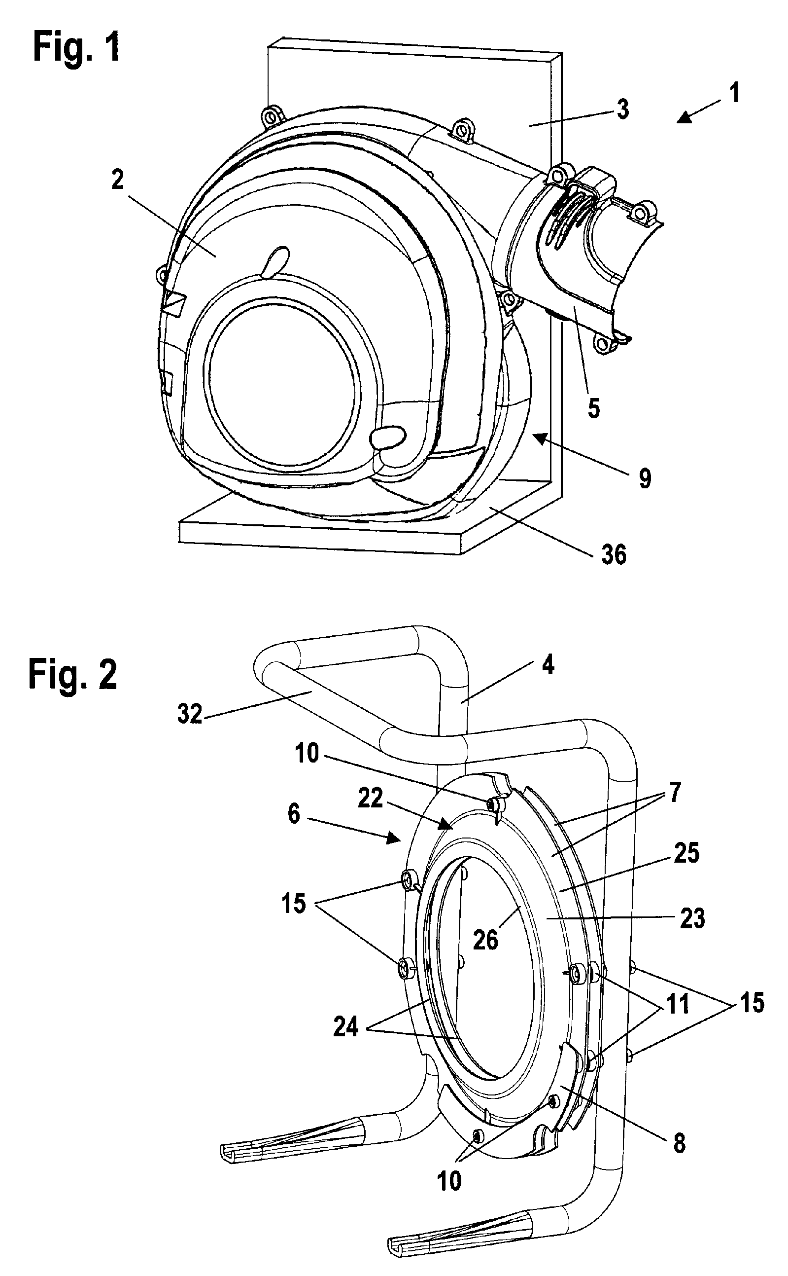
[0013]The blower apparatus 1 illustrated in FIG. 1 is designed to be carried on the back of the operator (backpack blower). The blower apparatus comprises an apparatus housing 2 in which a drive motor, in particular, an internal combustion engine, is arranged. The apparatus housing 2 of the blower apparatus 1 is arranged, preferably detachably, on a back support plate 3. On the back support plate 3 carrying straps (not illustrated) are arranged with which the blower apparatus is carried on the operator's back. The blower 1 has a blower tube 5 through which air is conveyed that is sucked in through the suction opening 9 formed between the apparatus housing 2 and the back support plate 3. A horizontal section 36 is provided on the back support plate 3 on which the apparatus housing 2 can be attached by means of a base (not illustrated in FIG. 1).

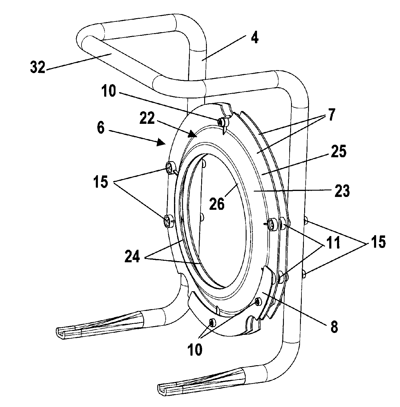
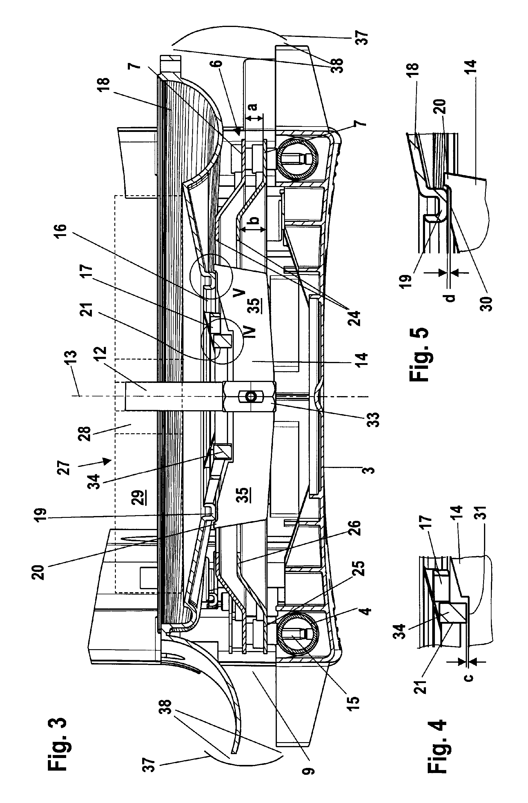
[0014]In FIG. 2, the tubular frame 4 of the back support plate 3 is illustrated in a perspective view; the access protection device 6 arrange...


PUM


Abstract

A blower apparatus has a blower housing having a blower intake. A motor-driven blower is arranged in the blower housing and takes in air in a flow direction through the blower intake into the blower housing. A device for mechanical clearing of the blower intake is arranged at the blower intake. The mechanical clearing device is driven in rotation during operation of the blower apparatus.

Description

BACKGROUND OF THE INVENTION[0001]The invention relates to a blower apparatus having a motor-driven blower that is arranged in a blower housing and takes in air into the blower housing through a blower intake.[0002]U.S. Pat. No. 6,305,048 discloses a backpack-style blower apparatus that is carried on the back of the operator. The blower apparatus comprises a blower wheel for sucking in air. In order to prevent that dirt particles are sucked in, a screen is arranged at the intake into the blower housing. Such a screen becomes easily clogged, for example, by leaves taken up by the suction flow. Leaves or dirt particles that pass through the screen can deposit within the blower housing and can lead to clogging of the blower. In order to clean the intake into the blower housing, the operator must first remove the blower apparatus from his back; therefore, work must be interrupted every time the screen must be cleaned.SUMMARY OF THE INVENTION[0003]It is an object of the present invention ...

Claims


Application Information

Patent Timeline
Patent Type & Authority Patents(United States)
IPC IPC(8): A47L5/00
CPCA01G1/125F04D29/703F04D23/003A47L5/14A01G20/47
Inventor KREMSLER, DIETERHOCQUEL, MICHAELLANGHANS, KLAUSSWISTUN, HELMUTGAESE, UWE
Owner ANDREAS STIHL AG & CO KG
Why Eureka
Try Eureka