Elevator assembly with extendable sill

a technology of extending sills and assembly parts, which is applied in the direction of mine lifts, transportation and packaging, building lifts, etc., can solve the problems of occupant ride quality problems, car guidance system component wear and tear, and ride quality declines

Inactive Publication Date: 2009-11-24
OTIS ELEVATOR CO
View PDF20 Cites 13 Cited by
  • Summary
  • Abstract
  • Description
  • Claims
  • Application Information

AI Technical Summary

Benefits of technology

[0052]The unique, extendable sill 38 allows for quicker installation of the car assembly and provides more running clearance, which results in a softer ride and decreased guidance system component wear. Further, because the running clearance is greater, the gaps to the landing sills are also increased, which decreases aerodynamic pulse events generated as the elevator moves past landings. An additional benefit includes the opportunity to use a simplified door moving mechanism and interlock that does not require high accuracy vanes that restrict the amount of float that the guidance system can use. The subject invention can also be used with less initial landing alignment accuracy because the sill can be extended and adjusted without introducing a step at the landing sill to accommodate slight misalignments between the car and the landing. This decreases sensor and drive systems needs and improves landing speed.
[0053]The preceding description is exemplary rather than limiting in nature. Variations and modifications to the disclosed examples may become apparent to those skilled in the art that do not necessarily depart from the essence of this invention. The scope of legal protection given to this invention can only be determined by studying the following claims.

Problems solved by technology

If the running clearance is minimized, ride quality is decreased and car guidance system component wear is increased.
If the running clearance is maximized, ride quality is improved but a large operating gap between the elevator car and a landing is created, which is undesirable.
One problem with this solution is that the lateral movement of the car creates occupant ride quality issues.
Another disadvantage with this system is that a large amount of energy is required to move the car in a lateral direction.
Further, if the system fails there is still a large gap between the car and the landing.

Method used


Image

  • Elevator assembly with extendable sill
  • Elevator assembly with extendable sill
  • Elevator assembly with extendable sill

Examples


Embodiment Construction

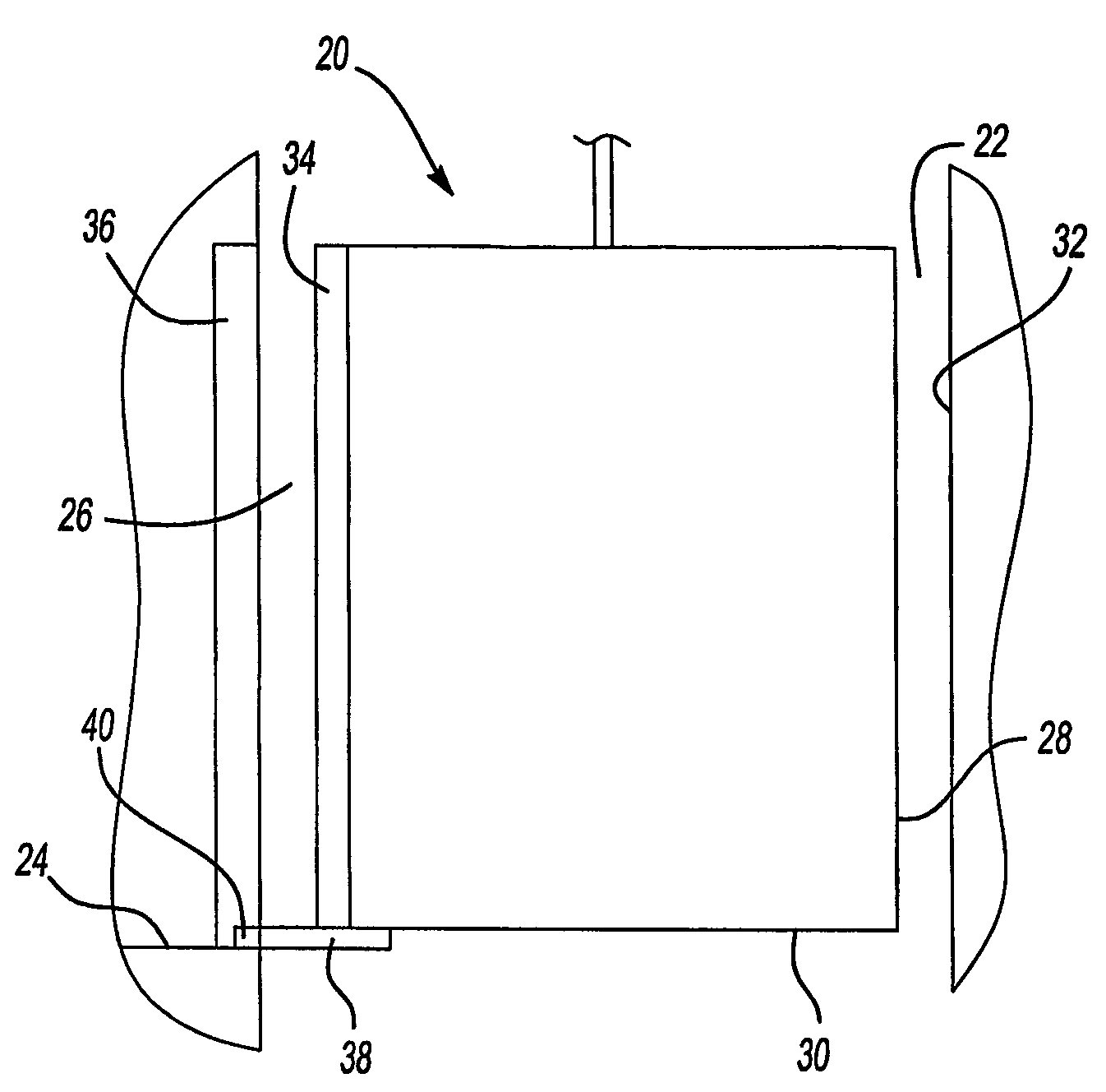
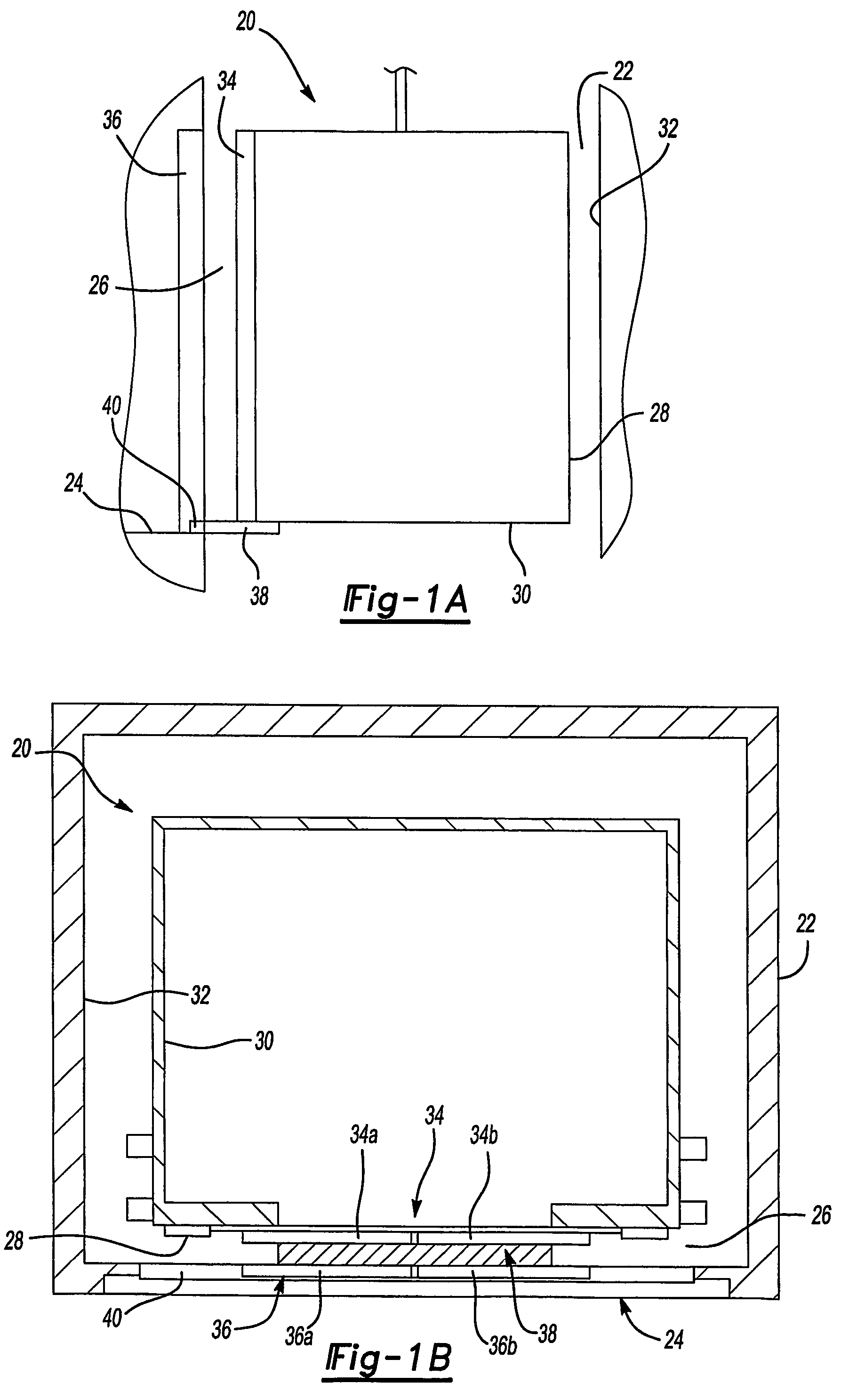
[0034]As seen in FIGS. 1A and 1B, an elevator assembly 20 is mounted within a hoistway 22 for movement between landings 24 (only one is shown). An operating gap 26 is maintained between an exterior surface 28 of an elevator car 30 and hoistway walls 32. The operating gap 26 is large enough to provide sufficient running clearance between the hoistway walls 32 and the elevator car 30 as the elevator assembly 20 moves within the hoistway 22 between landings 24.

[0035]The elevator car 30 includes an elevator door assembly 34 that moves between open and closed positions. When the elevator car 30 stops at one of the landings 24 to load or unload passengers or cargo, the elevator door assembly 34 aligns with a landing door assembly 36. A sill 38, supported by the elevator car 30, extends outwardly from the car 30 toward the landing door assembly 36 to bridge the operating gap 26 between the elevator door assembly 34 and the landing 24. The sill 38 extends out from underneath the elevator do...


PUM


Abstract

An elevator (20) includes a sill (38) that extends out from underneath an elevator car (30) to bridge an operating gap (26) between the car (30) and a landing (24). When an elevator door (34) is aligned with a landing door (36), the sill (38) extends outwardly from the car (30) until the sill (38) makes contact with a landing structure (40). A locking mechanism (52) securely locks the sill (38) to the landing structure (40). In one example, once proper sill alignment and locking engagement occurs, a door moving mechanism (50) is released and the elevator (34) and landing (36) doors open.

Description

FIELD OF THE INVENTION[0001]This invention generally relates to an elevator with an extendable sill that bridges an operating gap between an elevator car and a landing. More particularly, this invention relates to a sill that extends outwardly underneath an elevator door to engage a landing structure.DESCRIPTION OF THE RELEVANT ART[0002]Elevator cars move upwardly and downwardly within a hoistway between landings. Sufficient running clearance must be maintained between the exterior of the elevator car and the hoistway walls to allow the car to move quickly and efficiently within the hoistway. If the running clearance is minimized, ride quality is decreased and car guidance system component wear is increased. If the running clearance is maximized, ride quality is improved but a large operating gap between the elevator car and a landing is created, which is undesirable.[0003]One solution has been to use a pendulum car system. The pendulum car operates with an increased running clearan...

Claims


Application Information

Patent Timeline
Patent Type & Authority Patents(United States)
IPC IPC(8): B66B13/28B66B13/06B66B13/12B66B13/16B66B13/24B66B13/30B66B17/34
CPCB66B13/24B66B17/34B66B13/301B66B13/28B66B13/308
Inventor MILLER, ROBIN MIHEKUNGALANTE, TIMOTHY P.
Owner OTIS ELEVATOR CO
Why Eureka
Try Eureka