Motorcycle rear-wheel braking system operating mechanism

a technology of rear-wheel braking and operating mechanism, which is applied in the direction of braking system, cycle brake, cycle equipment, etc., can solve the problems of user movement being somewhat awkward, difficult to press down on the right foot pedal to brake, etc., and achieves the effect of safer driving in traffic or small in siz

Inactive Publication Date: 2009-11-24
WOLFE JOSEPH A
View PDF19 Cites 10 Cited by
  • Summary
  • Abstract
  • Description
  • Claims
  • Application Information

AI Technical Summary

Benefits of technology

[0010]The present invention aims to eliminate the problem of having a rear-wheel brake, solely activated by the right foot pedal, by wiring the brake foot pedal (from an extension placed at the rear of the pedal that functions as a lever) to a small hand lever mounted on the left handlebar, thereby allowing a secondary means of activation of the rear-wheel hydraulic braking system. The lever operates the rear wheel brake and effectively obviates the need to use the right foot pedal for rear-wheel braking. This is especially convenient for those who engage in rough motor-cross or motorcycle racing. The braking mechanism is more efficient and precise when it is operated with the lever on the left handlebar.
[0012]The rear-wheel brake lever is significantly smaller in size than the clutch lever, and it is designed where it can be rotated around the handlebar. It can be placed or shifted higher or lower on the handlebar, depending on the desires of the user and what is most comfortable for them. In this fashion, the left handlebar has a hand brake lever for the rear wheel hydraulic braking system for traveling at high speed and engaging in racing; it is also in a position where it is distinguishable from the larger clutch lever, which is significantly safer for driving in traffic or in urban areas.
[0013]Integral to the invention's design is the right foot pedal. It is similar in design to pre-existing motorcycle foot brake pedals with the same function of braking the motorcycle's rear wheel by depressing the pedal with the rider's right foot. The design feature of the extension on the rear of the pedal, with a wire cable connected and routed alongside the motorcycle frame to the front of the motorcycle to a hand brake lever mounted on the left handlebar, allows the pedal to change from a single method of activation. This is advantageous to the rider depending on how he / she chooses to utilize the braking system. Essentially, the brake pedal design allows a dual means of activation with either the right foot or left hand that is unique to motorcycles.

Problems solved by technology

Motorcyclists who engage in racing find it difficult at very high speeds (even at highway speeds) to press down upon the right foot pedal to brake.
This is due in part to the movement being somewhat awkward for the user.
At high speeds, even a small bump or a turn in the road can affect the foot from accurately pressing down upon the right foot pedal to brake; either the obstruction in the road or the angle of the foot impedes the motorcyclist from being confident in the ability to brake using the right foot pedal, thereby slowing down the rear wheel.
Obviously, using the front-wheel brake on the right handlebar, while it is an easier and more precise movement for the motorcyclist, can be dangerous, as the front wheel could skid, causing loss of control, or in an extreme scenario the motorcycle could risk flipping over in a forward direction; the front wheel is braking while the back wheel is still going full-speed.
This seems like an obvious solution, but the right handlebar already comprises the twist-grip throttle control and front-wheel brake lever, so placing another brake lever there is not a viable solution.
Mistaking the rear-wheel brake lever for the clutch is also a dangerous possibility, especially in heavy, stop-and-go traffic.
This comprises an entirely different issue, which relates more to the steering of the motorcycle than the operation of the brakes.
The user can use the brake handle as a single (rear-wheel only) or a double brake, which can be considered inconvenient since both of the brakes are on the same lever.

Method used


Image

  • Motorcycle rear-wheel braking system operating mechanism
  • Motorcycle rear-wheel braking system operating mechanism
  • Motorcycle rear-wheel braking system operating mechanism

Examples


Embodiment Construction

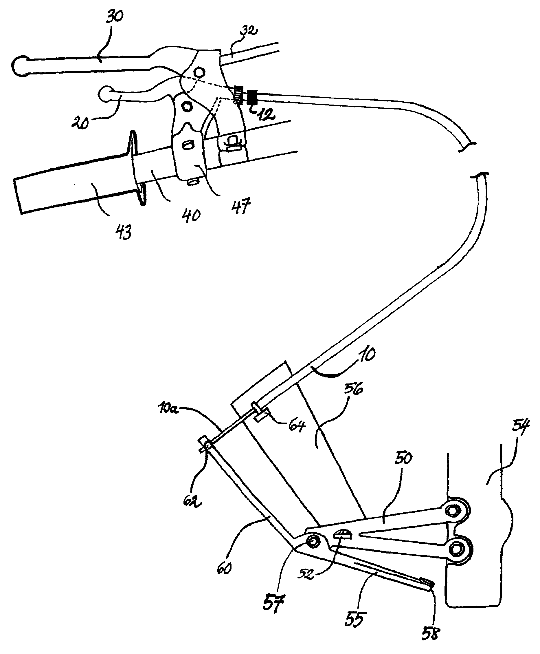
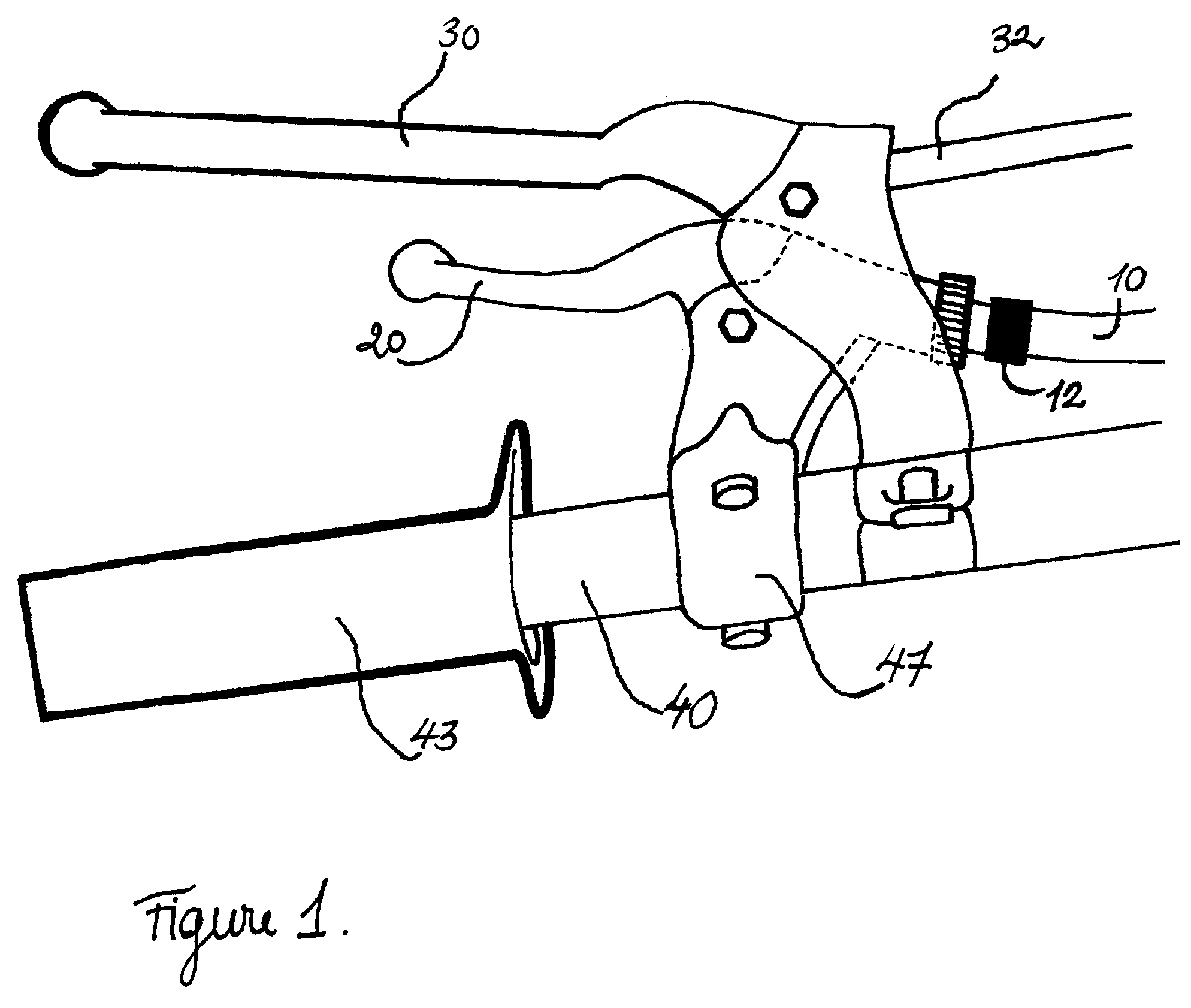
[0017]The present invention is an interconnected operating mechanism for a motorcycle hydraulic rear-wheel braking system. As shown in FIG. 1 of the present invention, on the motorcycle left handlebar 40 there is a wire cable 10. The wire cable 10 that is used preferably consists of an inner steel wire cable with a flexible outer casing, similar to what is used on most motorcycle control systems. The wire cable 10 is functionally connected to the rear-wheel hand brake lever 20, mounted on the handlebar 40 by a clamping mechanism 47 typical to motorcycle control levers. The rear-wheel brake lever 20 is mounted and rotated downward under the larger clutch lever 30 mounted inboard on the handlebar 40. The positioning of the rear-wheel brake lever 20 and the clutch lever 30 is defined with respect to their linear position along the longitudinal axis of the handlebar 40. There is ample room between the two levers 20 and 30 on the left handlebar 40 to ensure safe and efficient operation. ...


PUM


Abstract

A mechanism for placing a hand operated rear-wheel brake lever of a motorcycle on the left handlebar of the motorcycle. A steel wire is routed from the right foot brake pedal by an extension to a small lever found under the clutch hand lever on the left handlebar. When the lever is pulled inward, the wire pulls the right foot brake pedal up, activating the hydraulically operated braking system of the motorcycle's rear wheel without the rider having to use his / her right foot. Riders who engage in racing or who are traveling at high speeds have greater precision in their ability to brake the rear wheel of their vehicle.

Description

FIELD OF THE INVENTION[0001]The present invention relates to a rear-wheel braking system mechanism for motorcycles that is activated by a wire cable and operated with a mounted lever on the left handlebar.BACKGROUND OF THE INVENTION[0002]In a typical motorcycle, and unlike a bicycle, the clutch is found on the left handlebar. The twist-grip throttle control and the front-wheel brake lever are two different controls on the right handlebar. The right foot pedal is where the brake for the rear wheel is normally found.[0003]Motorcyclists who engage in racing find it difficult at very high speeds (even at highway speeds) to press down upon the right foot pedal to brake. This is due in part to the movement being somewhat awkward for the user. At high speeds, even a small bump or a turn in the road can affect the foot from accurately pressing down upon the right foot pedal to brake; either the obstruction in the road or the angle of the foot impedes the motorcyclist from being confident in...

Claims


Application Information

Patent Timeline
Patent Type & Authority Patents(United States)
IPC IPC(8): F16D65/14
CPCB60T7/06B60T7/102Y10T74/2022B62L3/02
Inventor WOLFE, JOSEPH A.
Owner WOLFE JOSEPH A
Why Eureka
Try Eureka