Method and device for removing mercury

a technology of mercury and mercury removal, applied in the direction of machines/engines, chemical/physical processes, process and machine control, etc., can solve the problems of inconvenient treatment shortened life of the plant, and high cost of large amount of exhaust gas treatmen

Active Publication Date: 2009-11-24
MITSUBISHI POWER LTD
View PDF24 Cites 42 Cited by
  • Summary
  • Abstract
  • Description
  • Claims
  • Application Information

AI Technical Summary

Problems solved by technology

Exhaust gas generated by combusting coal or heavy oil may contain harmful or toxic material such as soot, sulfur oxide (SOx), nitrogen oxide (NOx), and metal mercury.
However, because this method requires sorbent injection devices and larger-scale sorbent collectors, or a special type of absorption removal means, it is costly and not suitable for the treatment of large amount of exhaust gas such as those exhausted from power plants.
However, because hydrochloric gas is highly corrosive, if the chlorinating agent is added in surplus, it causes corrosion of the flue or a downstream device in the system, and therefore, there is a problem that the life of the plant is shortened.
However, it is costly and not economical for the treatment of large amount of exhaust gas.
If neutral salt slurry such as sodium chloride (NaCl) is used, because it not decompose at the operating temperature of the denitration equipment, a desired effect cannot be obtained, possibly causing clogging.

Method used


Image

  • Method and device for removing mercury
  • Method and device for removing mercury
  • Method and device for removing mercury

Examples


first embodiment

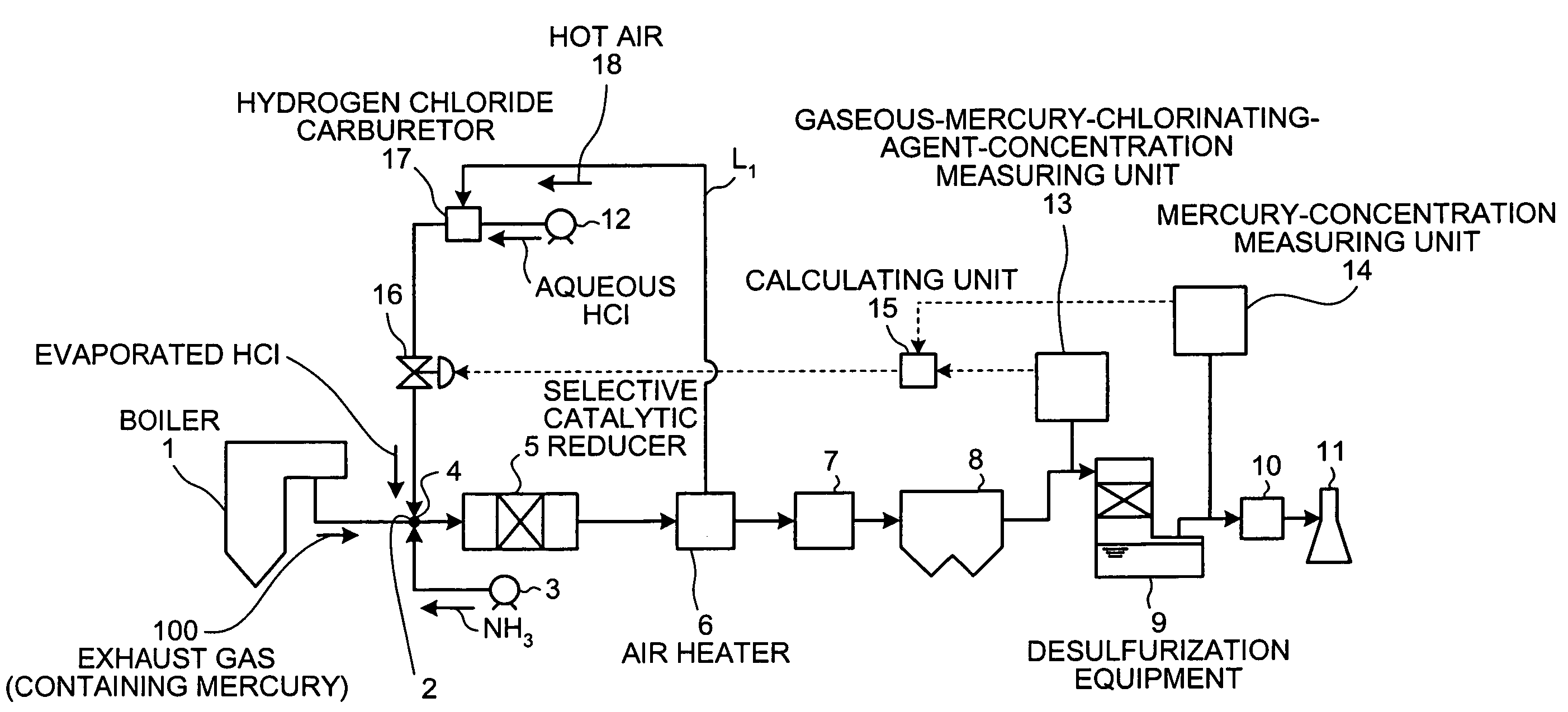
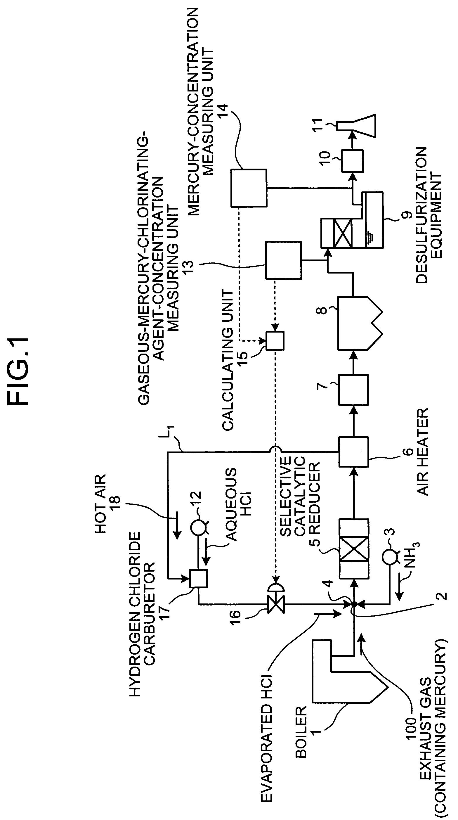
[0022]As shown in FIG. 1, the mercury removing device from a mercury-containing exhaust gas includes a hydrogen chloride carburetor 17 that supplies evaporated HCl that has been evaporated by being directly heated by a hot air 18, a selective catalytic reducer 5 that injects / supplies the evaporated HCl at an injection point 4 provided on a flue to an exhaust gas 100, which contains nitrogen oxide, sulfur oxide, and mercury, and that is exhausted from a boiler 1, and that removes the nitrogen oxide from the exhaust gas 100 to which the evaporated HCl has been supplied, an air heater 6 that heats the exhaust gas 100 from which nitrogen oxide has been removed, a heat recovering member 7 that recovers heat from the heated exhaust gas by hear exchange, a precipitator 8 that removes soot and dust from the exhaust gas 100, a desulfurization equipment 9 that removes the sulfur oxide from the exhaust gas 100, a reheater 10 that raises the temperature of the exhaust gas 100, and a flue gas s...

second embodiment

[0065]FIG. 3 is a schematic of a mercury removing device from a mercury-containing exhaust gas according to the present invention.

[0066]As shown in FIG. 3, the mercury removing device from a mercury-containing exhaust gas according to the second embodiment includes the hydrogen chloride carburetor 17 that supplies evaporated HCl as the mercury-chlorinating agent to the exhaust gas 100, which contains nitrogen oxide, sulfur oxide, and mercury, and that is exhausted from the boiler 1, the selective catalytic reducer 5 that removes nitrogen oxide from the exhaust gas 100 to which the evaporated HCl is supplied, the air heater 6 and the heat recovering member 7 that heat the exhaust gas 100 from which nitrogen oxide has been removed, the precipitator 8 that removes soot and dust from the exhaust gas 100, the desulfurization equipment 9 that removes sulfur oxide from the exhaust gas 100, the reheater 10 that raises a temperature of the exhaust gas 100, and the flue gas stack 11 that emit...


PUM

PropertyMeasurementUnit
temperatureaaaaaaaaaa
operating temperatureaaaaaaaaaa

Abstract

A mercury removing device includes a gasification unit that converts a non-gaseous-mercury-chlorinating agent, which is non-gaseous at room temperature and normal pressure, into gaseous-mercury-chlorinating agent by heating the non-gaseous-mercury-chlorinating agent with heat of hot air generated by using the exhaust gas or hot air generated by using an air heater installed in a flue that conveys the exhaust gas. The gaseous-mercury-chlorinating agent produced in this manner is supplied to the exhaust gas in the flue.

Description

BACKGROUND OF THE INVENTION[0001]1. Field of the Invention[0002]The present invention relates to a technology for removing mercury contained in an exhaust gas.[0003]2. Description of the Related Art[0004]Exhaust gas generated by combusting coal or heavy oil may contain harmful or toxic material such as soot, sulfur oxide (SOx), nitrogen oxide (NOx), and metal mercury.[0005]Recently, various techniques have been devised for treating metal mercury in combination with denitration equipment that reduce NOx and wet desulfurization equipment that use alkali absorbing solution as an SOx absorbent.[0006]As a method of treating metal mercury in the exhaust gas, a method of using a sorbent is widely known. The sorbent can be an activated carbon or a selenium filter. However, because this method requires sorbent injection devices and larger-scale sorbent collectors, or a special type of absorption removal means, it is costly and not suitable for the treatment of large amount of exhaust gas suc...

Claims


Application Information

Patent Timeline
Patent Type & Authority Patents(United States)
IPC IPC(8): B01D53/50B01D53/56B01D53/64B01D53/74B01D53/75B01D53/76
CPCB01D53/64B01D53/75B01D53/77B01D53/86F23J2215/60B01D2251/502B01D2257/302B01D2257/404B01D2257/602B01D2251/206Y02A50/20Y10S423/05
Inventor HONJO, SHINTAROOKINO, SUSUMUTAKEUCHI, YASUHIROKAGAWA, SEIJINAKAYAMA, YOSHIO
Owner MITSUBISHI POWER LTD
Why Eureka
Try Eureka