Video encoding methods and devices

a technology of video encoding and video data, applied in the field of video encoding, can solve the problems of degrading the video being placed on the channel, and affecting the quality of the video being encoded, so as to reduce the complexity of operations

Inactive Publication Date: 2009-11-24
RGT UNIV OF CALIFORNIA
View PDF4 Cites 21 Cited by
  • Summary
  • Abstract
  • Description
  • Claims
  • Application Information

AI Technical Summary

Benefits of technology

[0004]A video codec of a preferred embodiment is suitable for implementation on a variety of platforms, including platforms where devices require both encoding and decoding engines. Various features of preferred embodiment codecs reduce complexity for operations such as motion determination. Channel resources are allocated in preferred embodiments unequally, with an allocation being determined based upon channel conditions and the error level in a frame being encoded. A decoder of a preferred embodiment, provided with an error frame and motion vector information may conduct decoding with motion compensation. In an example encoder of the invention, a motion estimator identifies motion vectors using a phase plane correlation technique based on phase quantization, where the phase difference between the Fourier transformed version of blocks in a reference frame and a current frame is estimated by dividing the complex plane into sectors and assigning the Fourier domain difference to the sectors.

Problems solved by technology

Digital communication and storage of video data is a difficult task due to the sheer volume of digital data required to accurately describe a video sequence.
In video, the amount of data quickly becomes very large.
Channel conditions, especially in wireless environments and in applications where significant amounts of data is exchanged, as in video conferencing, may degrade the video being placed on the channel or slow the communication if the channel conditions are not accounted for in the video encoding strategy.
Accordingly, high encoder complexity can limit application of the standards.

Method used


Image

  • Video encoding methods and devices
  • Video encoding methods and devices
  • Video encoding methods and devices

Examples


Embodiment Construction

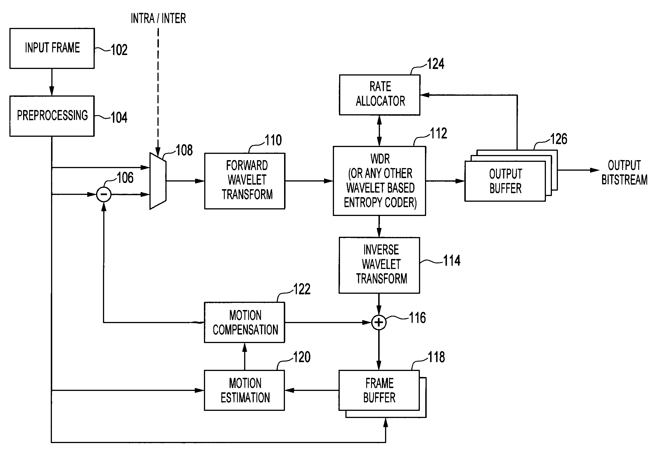
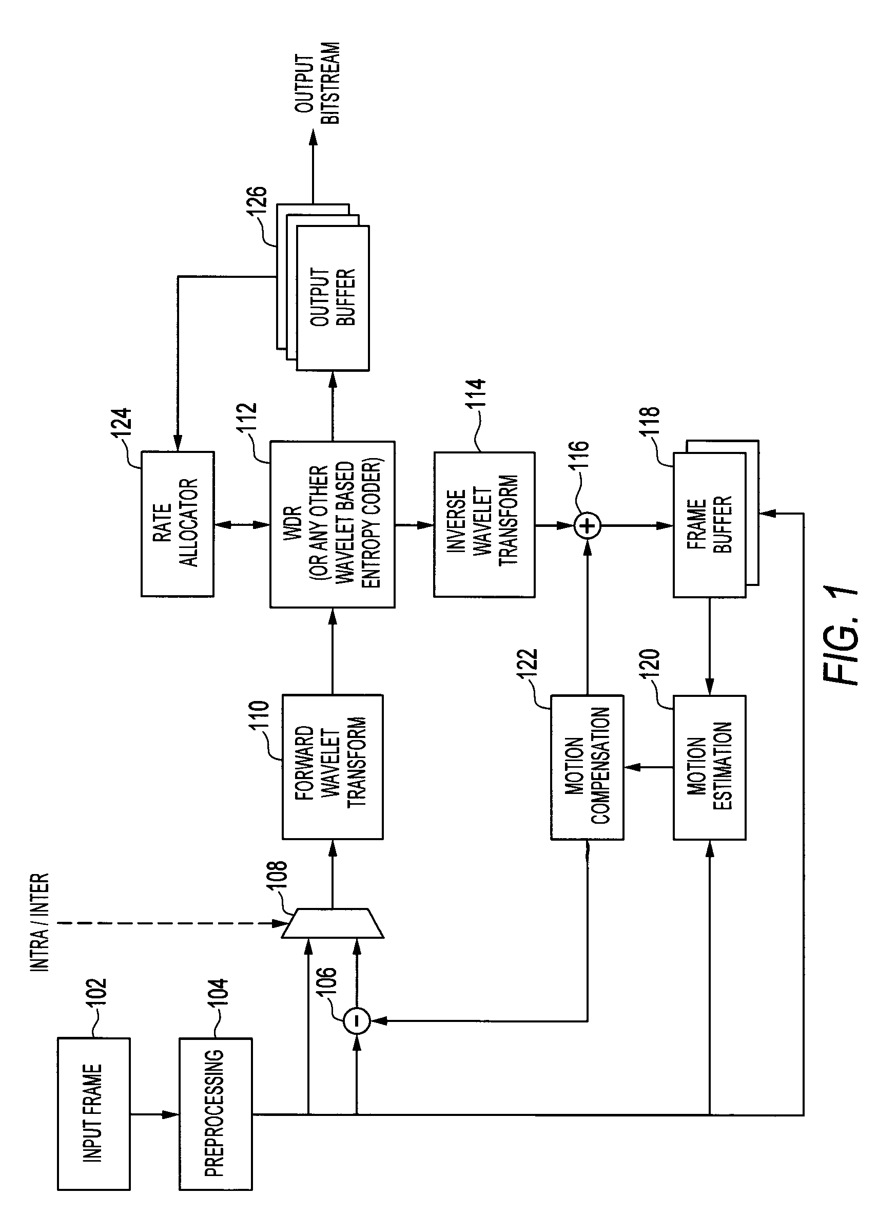
[0012]The invention is directed to methods, devices and systems for encoding video data. Embodiments of the invention provide coding that is responsive to the channel upon which the encoded data will be transmitted, and also the nature of the video data, to achieve good quality encoding that makes an efficient use of the channel.

[0013]In describing the preferred embodiments, and setting forth the scope of the invention in the claims, the term “frame” encompasses both video frames and portions thereof. Method steps and device components typically operate on portions of video frames, as is known in the art, and such portions may be referred to as blocks, sub-blocks, windowed portions, etc. The term “frame” as used herein therefore encompasses both entire video frames and portions thereof, such as blocks and sub-blocks or selected portions of the frame. Frame, as used herein, could also be used to describe the entire frame or its decimated version or processed version. The term “frame”...


PUM


Abstract

A video codec of a preferred embodiment is suitable for implementation on a variety of platforms, including platforms where devices require both encoding and decoding engines. Various features of preferred embodiment codecs reduce complexity for operations such as motion determination. Channel resources are allocated in preferred embodiments unequally, with an allocation being determined based upon channel conditions and the error level in a frame being encoded. A decoder of a preferred embodiment, provided with an error frame and motion vector information may conduct decoding with motion compensation. In an example encoder of the invention, a motion estimator identifies motion vectors using a phase plane correlation technique based on phase quantization, where the phase difference between the Fourier transformed version of blocks in a reference frame and a current frame is estimated by dividing the complex plane into sectors and assigning the Fourier domain difference to the sectors.

Description

FIELD OF INVENTION[0001]A field of the invention is video encoding. Other fields of the invention include video processing, digital communications and digital storage of video data.BACKGROUND[0002]Digital communication and storage of video data is a difficult task due to the sheer volume of digital data required to accurately describe a video sequence. In video, the amount of data quickly becomes very large. A block-based motion estimation algorithm is an efficient method to describe the motion between image and video data. With motion estimation, the amount of data needed to describe, for example, a video sequence may be greatly reduced, as are the demands on storage media and channels, whether internal hardware channels or communication media. Channel conditions, especially in wireless environments and in applications where significant amounts of data is exchanged, as in video conferencing, may degrade the video being placed on the channel or slow the communication if the channel ...

Claims


Application Information

Patent Timeline
Patent Type & Authority Patents(United States)
IPC IPC(8): G06K9/36G06K9/46H04N7/26H04N7/46
CPCG06F17/148H04N19/85H04N19/59H04N19/139H04N19/172H04N19/149H04N19/63H04N19/115H04N19/61H04N19/37H04N19/132H04N19/136H04N19/152H04N19/156H04N19/164H04N19/635H04N19/43H04N19/547H04N19/587H04N19/86H04N19/13
Inventor MOLINO, ANDREAVACCA, FABRIZIOBISWAS, MAINAKNGUYEN, TRUONG
Owner RGT UNIV OF CALIFORNIA
Why Eureka
Try Eureka