Combustion pressure sensor

a sensor and combustion pressure technology, applied in the direction of engine testing, structural/machine measurement, instruments, etc., can solve the problems of undesired load deviation in the preliminary pressure exerted on the pressure sensor, and erroneous output different from the correct output to be inevitably generated, so as to minimize the deviation of the preliminary pressure and achieve high reliability.

Inactive Publication Date: 2009-12-01
DENSO CORP
View PDF11 Cites 13 Cited by
  • Summary
  • Abstract
  • Description
  • Claims
  • Application Information

AI Technical Summary

Benefits of technology

[0009]The present invention has been completed with the above view in mind and has an object to provide a combustion pressure sensor for an internal combustion engine that is effective in highly minimizing a deviation of a preliminary pressure occurring when mounting the combustion pressure sensor to the engine to allow a pressure sensor to generate a correct combustion pressure in a highly reliable manner.
[0013]With such a structure, during the occurrence of the compressive contraction of the housing, the transfer member moves to generate the load in the same direction as that in which the flexible portion of the seal member stretches. In addition, the facing portion has rigidity lower than that of the orthogonal planar portion. This enables the facing portion of the seal member to reliably absorb the variation in load acting on the pressure sensor resulting from the movement of the transfer member.
[0015]With such a structure, forming the flexible portion in the corrugated shape enables a reduction in rigidity of the seal member while increasing a length of the flexible portion. This enables the flexible portion of the seal member to more reliably absorb the load acting on the pressure sensor caused by the movement of the transfer member.
[0017]With such a structure, the flexible portion with low rigidity can reliably absorb the load acting on the pressure sensor resulting from the movement of the transfer member due to the compressive contraction of the housing. In addition, the orthogonal planar portion of the seal member plays a role as a part required for the housing and the transfer member to be connected to each other, that is, an inevitable part. Forming the flexible portion in such a part enables the seal member to be formed in a reduced body size.
[0019]With such a structure, forming the flexible portion in the corrugated shape enables a reduction in rigidity of the seal member. This enables the flexible portion of the seal member to more reliably absorb the adverse affect acting on the pressure sensor caused by the movement of the transfer member.

Problems solved by technology

Upon the occurrence of such an axial movement to transfer a load to the pressure sensor, the pressure sensor is subjected to an undesired load.
This results in a deviation in the preliminary pressure exerted to the pressure sensor.
This results in a fear of the initially exerted preliminary pressure being deviated, causing an erroneous output different from a correct output to be inevitably generated.

Method used


Image

  • Combustion pressure sensor
  • Combustion pressure sensor
  • Combustion pressure sensor

Examples


first embodiment

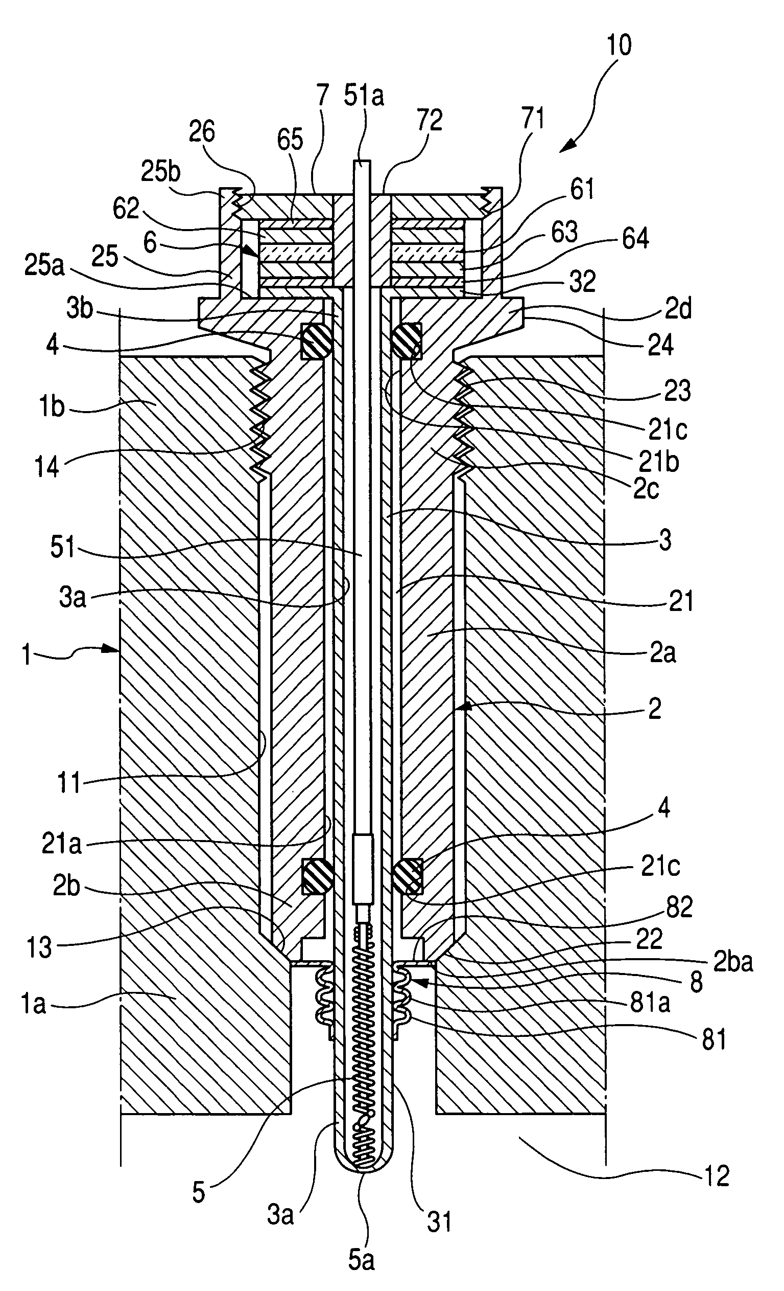
[0025]Now, a combustion pressure sensor 10 of an embodiment according to the present invention is described below in detail with reference to FIG. 1.

[0026]FIG. 1 is a longitudinal cross sectional view showing the combustion pressure sensor 10 of the present embodiment under a state mounted on an engine head 1 of a diesel engine.

[0027]As shown in FIG. 1, the engine head 1 is formed with a through-bore 11 in fluid communication with a combustion chamber 12 of the diesel engine. The through-bore 11 has an inward area 1a, formed with an annular tapered shoulder 13 in the form of a stepped portion, and an outward 1b formed with a female-threaded portion 14.

[0028]Hereunder, a structure of the combustion pressure sensor 10 is described below in detail with reference to FIG. 1.

[0029]The combustion pressure sensor 10 includes a metallic housing 2 disposed in the through-bore 11 of the engine head 1. The housing 2 includes a substantially cylindrical housing body 2a in which an axially extend...


PUM

PropertyMeasurementUnit
combustion pressureaaaaaaaaaa
pressureaaaaaaaaaa
rigidityaaaaaaaaaa

Abstract

A combustion pressure sensor for detecting a combustion pressure in a combustion chamber of an engine is disclosed as having a housing mounted to an engine head in a gastight structure, a pressure sensor carried on the housing at a base end portion thereof, a transfer member having a pressure-receiving portion exposed to the combustion chamber to be axially slidable in the housing to transfer a combustion pressure from the combustion chamber to the pressure sensor, and a seal member disposed between the pressure-receiving portion of the transfer member and the housing in a gastight sealing structure to block an intrusion of combustion gas from the combustion chamber into the housing. The seal member includes a flexible portion with low rigidity that can stretch and absorb load acting on the pressure sensor when mounting the housing onto an engine cylinder.

Description

CROSS REFERENCE TO RELATED APPLICATIONS[0001]This application is related to Japanese Patent Application No. 2006-169573, filed on Jun. 20, 2006, the content of which is hereby incorporated by reference.BACKGROUND OF THE INVENTION[0002]1. Technical Field of the Invention[0003]The present invention relates to combustion pressure sensors for use in internal combustion engines and, more particularly, to a combustion pressure sensor for detecting a combustion pressure in an internal combustion engine such as an automotive diesel engine combined with a glow plug function for preheating an air-fuel mixture.[0004]2. Description of the Related Art[0005]In related art, an attempt has heretofore been made to provide a combustion pressure sensor combined with a glow plug function for a diesel engine, with one exemplary structure being disclosed in Japanese Patent Application Publication No. 2005-90954. With such a structure of the combustion pressure sensor, a glow plug body includes an upper p...

Claims


Application Information

Patent Timeline
Patent Type & Authority Patents(United States)
IPC IPC(8): G01L23/22
CPCG01L23/00F23Q7/001F23Q2007/002
Inventor HIROSE, YOSHINOBUWATARAI, TAKEHIRO
Owner DENSO CORP
Why Eureka
Try Eureka