
Energy recoverable wheel motor

Active Publication Date: 2009-12-01
WILLIAMS KEVIN
View PDF45 Cites 30 Cited by
  • Summary
  • Abstract
  • Description
  • Claims
  • Application Information

AI Technical Summary

Benefits of technology

[0015]In the present invention, the energy transfer means includes an induction stator or rotor positioned adjacent to the brake disk. In one embodiment of the present invention, the calipers can be affixed to the induction rotor. The induction rotor can include a conductive outer ring with a plurality of radially-spaced bars radiating toward the conductiv

Problems solved by technology

While flywheels are well known in the art, there is very little application of flywheels to moving vehicles.
However, flywheels have not been used for the storage of kinetic energy within the automobile.

Method used


Image

  • Energy recoverable wheel motor
  • Energy recoverable wheel motor
  • Energy recoverable wheel motor

Examples


Embodiment Construction

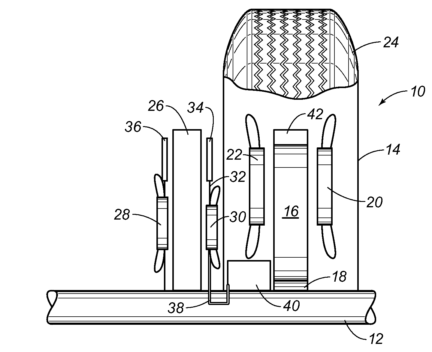
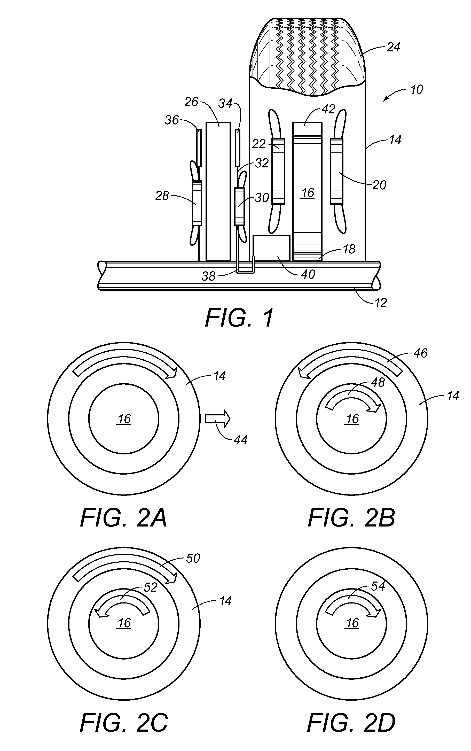
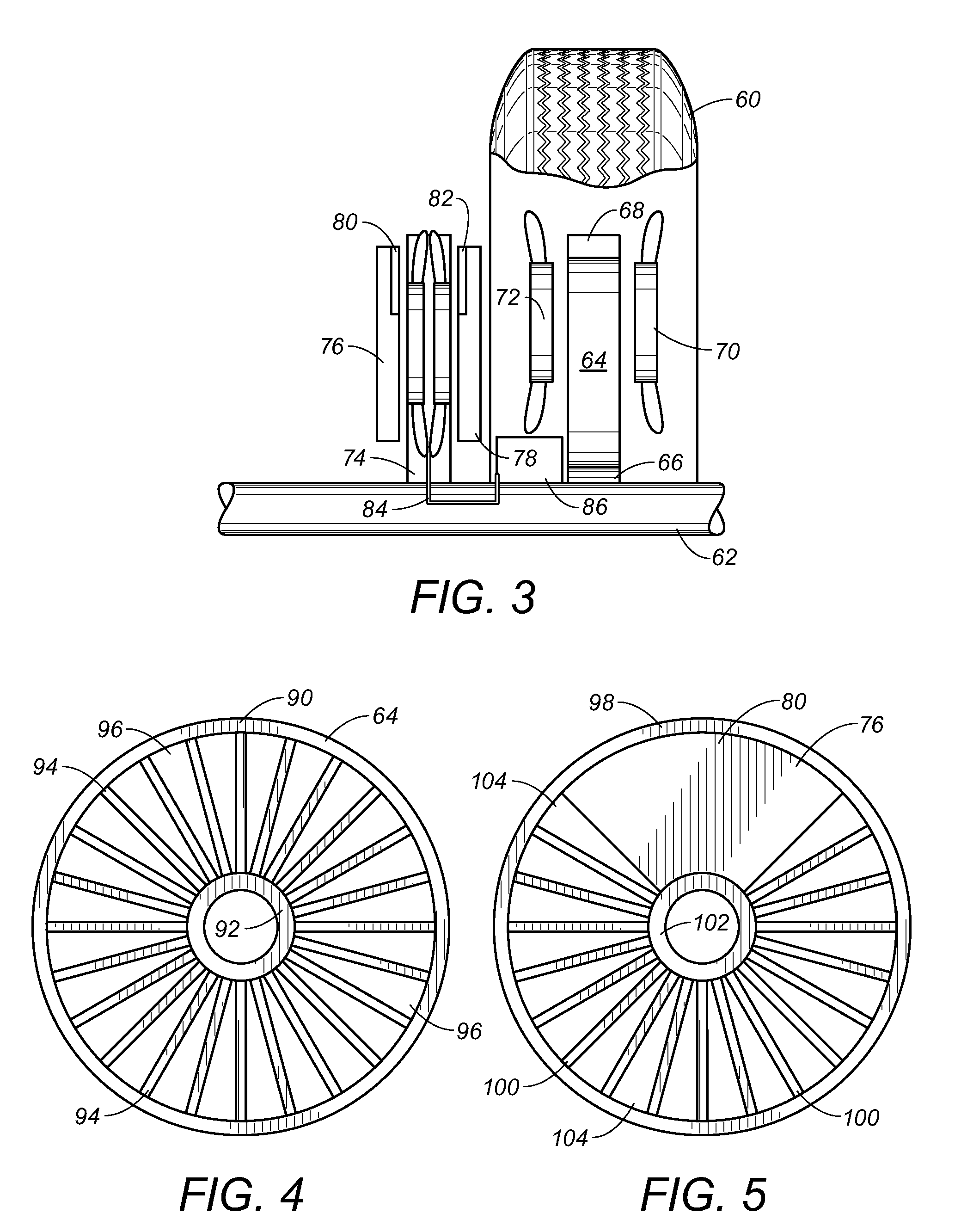
[0023]Referring to FIG. 1, there is shown the vehicle energy recovery system 10 in accordance with a simple embodiment of the present invention. The vehicle recovery system 10 includes an axle 12 having a wheel 14 affixed thereto. The wheel 14 will rotate with the rotation of the axle 12. A flywheel 16 is mounted in or adjacent to the wheel 14. The flywheel 16 is rotatable independent of the rotation of the axle 12. A secondary bearing 18 is interposed between the axle 12 and the flywheel 16 so as to allow the flywheel 16 to rotate independently of the axle 12. Induction rotor stators 20 and 22 are mounted on opposite sides of the flywheel 16. The stators 20 and 22 will rotate with the rotation of the wheel 14. The stators 20 and 22 are located in proximity to and on opposite sides of the flywheel 16 so as to be properly energized in a generator motor during the acceleration of the vehicle and during the rotational acceleration of the wheel 14 and its associated tire 24.

[0024]A brak...


PUM


Abstract

A vehicle energy recovery system has an axle, a wheel affixed to the axle so as to rotate with a rotation of the axle, a flywheel assembly mounted in or adjacent to the wheel so as to be rotatable independently of the rotation of the axle, a stator positioned in proximity to the flywheel assembly, a brake disk affixed to the axle and extending radially outwardly therefrom, and an energy transfer system cooperative with the brake disk for transferring energy from the brake disk to the flywheel assembly. A pair of calipers are respectively mounted adjacent opposite sides of the brake disk. The energy transfer system can be an induction stator or rotor positioned adjacent to the brake disk.

Description

RELATED U.S. APPLICATIONS[0001]The present application claims priority from U.S. Provisional Application Ser. No. 60 / 701,155, filed on Jul. 22, 2005, and entitled “Energy Recoverable Wheel Motor”.STATEMENT REGARDING FEDERALLY SPONSORED RESEARCH OR DEVELOPMENT[0002]Not applicable.REFERENCE TO MICROFICHE APPENDIX[0003]Not applicable.FIELD OF THE INVENTION[0004]The present invention relates to systems for recovering the braking energy of a vehicle. Additionally, the present invention relates to flywheel systems which receive kinetic energy for storage and for transmitting such kinetic energy for use. Additionally, the present invention relates to flywheel energy systems in which the flywheel is incorporated into the wheel of the vehicle whereby the braking energy can be used for the acceleration of the vehicle and where acceleration energy can be used for the braking of the vehicle.BACKGROUND OF THE INVENTION[0005]While flywheels are well known in the art, there is very little applicat...

Claims


Application Information

Patent Timeline
IPC IPC(8): B60K6/00B60K1/00B60K8/00
CPCB60K6/105B60K6/34B60K7/0007Y02T10/92B60K2007/0061B60L2220/46Y02T10/6204B60K2007/0038Y02T10/62
Inventor WILLIAMS, KEVIN
Owner WILLIAMS KEVIN
Learn More