Device having sealed breakable chambers for storing and dispensing viscous substances

US7625114B2Inactive Publication Date: 2009-12-01KETTENBACH GMBH & CO KG

Image

  • Device having sealed breakable chambers for storing and dispensing viscous substances
  • Device having sealed breakable chambers for storing and dispensing viscous substances
  • Device having sealed breakable chambers for storing and dispensing viscous substances

Examples


Embodiment Construction

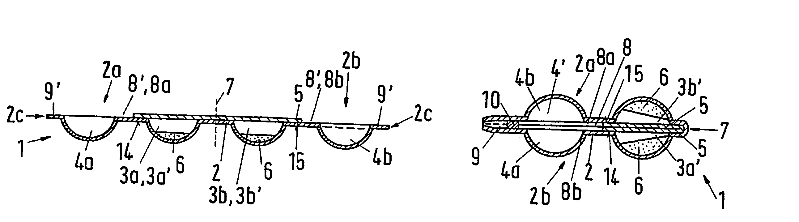
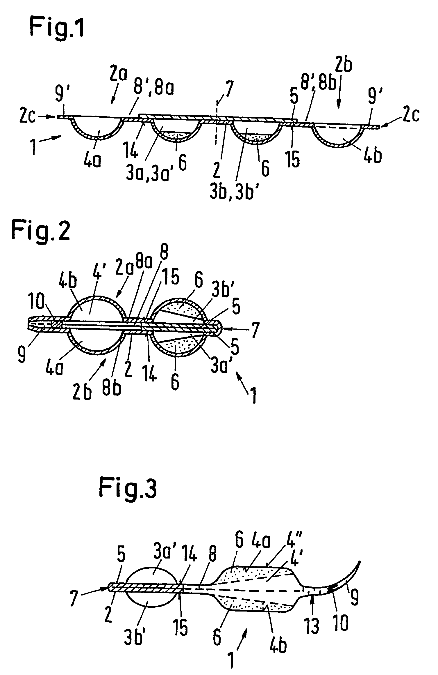
[0069]In the embodiment of a storage and dispensing device 1 illustrated in FIGS. 1 and 2, a carrier 2 has four depressions 3a, 3b; 4a, 4b at first arranged in series, specifically with mirror symmetry relative to a bending line 7. In the production of the storage and dispensing device 1, the components to be mixed with one another are introduced into the two center depressions 3a, 3b. Also, only these center depressions 3a, 3b are closed off with a film 5, to form two center chambers 3a′, 3b′. Closing takes place in such a manner that in each instance, one channel half 8′ to the adjacent depressions 4a, 4b remains free, with the interposition of a planned breakage point 14 and 15, respectively.

[0070]Between the two center chambers 3a′, 3b′, the strip-like carrier 2 has the bending line 7 that runs crosswise to the longitudinal expanse of the carrier 2, as already mentioned. By way of this line, the right carrier segment 2b in FIG. 1 can be folded onto the left carrier segment 2a in...


PUM

PropertyMeasurementUnit
Currentaaaaaaaaaa
Distanceaaaaaaaaaa
Resilienceaaaaaaaaaa

Abstract

The invention relates, among other things, to a device for storing and dispensing viscous substances, which are to be mixed from at least two components for use, having a film-like carrier, for example, in which at least three or four depressions are formed, for example arranged next to one another in a row, which are open towards the top, at first, so that one of the components, in each instance, can be introduced from the top into one of two center depressions, in each instance, i.e. depressions that are adjacent and are arranged at essentially the same distance from a bending line, and afterwards, the two center depressions can be sealed with a cover film, towards the outside, forming a chamber, in each instance, in such a manner that between each center chamber and at least one adjacent outer depression, a connection channel that opens towards at least one outer depression when pressure is applied to the center chamber, in each instance, by way of a planned breakage point, remains.

Description

CROSS REFERENCE TO RELATED APPLICATIONS[0001]Applicants claim priority under 35 U.S.C. §119 of German Application No. 102 51 050.4 filed on Nov. 2, 2002 and German Application No. 203 09 546.4 filed on Jun. 20, 2003. Applicants also claim priority under 35 U.S.C. §365 of PCT / EP03 / 11719 filed on Oct. 23, 2003. The international application under PCT article 21(2) was not published in English.BACKGROUND OF THE INVENTION[0002]1. Field of the Invention[0003]The invention relates to a device for storing and dispensing viscous substances. In this connection, viscous is understood to mean all substances capable of flow, i.e. liquid to paste-like substances, which can also be gel-like, for example. For use, the substances can be mixed from at least two components. The components themselves can also be viscous, but not all of them have to be viscous, only at least one does.[0004]The viscous substances are, for example, adhesives or sealing materials, such as those used in dental technology. ...

Claims


Application Information

Patent Timeline
01 Dec 2009
Publication
US7625114B2
IPC
B65D81/32; B65D75/32; B65D75/34; B65D75/58
CPC
B65D75/327; B65D81/3266; B65D75/5811; B65D75/34; B65D2575/3218
Inventors
SUCHAN, MATTHIAS; BUBLEWITZ, ALEXANDER