Rotation speed detecting apparatus and automatic transmission controller having the apparatus

a technology of automatic transmission controller and detecting apparatus, which is applied in the direction of mechanical equipment, instruments, etc., can solve the problems of gear shift shock, affecting the accuracy of detecting the rotation speed of each rotating member, etc., and achieve the effect of improving the accuracy of speed change control

Active Publication Date: 2009-12-01
TOYOTA JIDOSHA KK
View PDF8 Cites 6 Cited by
  • Summary
  • Abstract
  • Description
  • Claims
  • Application Information

AI Technical Summary

Benefits of technology

[0016]According the present invention, the detection period of the pulse signals from the first sensor used for determining the rotation speed of the first rotating member can be matched with the detection period of the output signals from the second sensor, to detect the rotation speeds of the first and second rotating members using the matched detection periods. As a result, consistent accuracy can be maintained between detections of the rotation speeds of the rotating members. Further, because the speed change control of the automatic transmission is performed based on the rotation speeds of the input and output shafts having the consistent accuracy, accuracy in speed change control can be improved.

Problems solved by technology

Such a difference in the length of response delay time results in a problem that accuracy of detecting the rotation speed varies for each rotating member.
In the detection, if the accuracy of detecting the rotation speed is inconsistent between the input shaft and the output shaft, accuracy of the speed change control is in turn lowered, thereby causing gear shift shock to occur during switching of a frictional engagement device to be engaged.

Method used


Image

  • Rotation speed detecting apparatus and automatic transmission controller having the apparatus
  • Rotation speed detecting apparatus and automatic transmission controller having the apparatus
  • Rotation speed detecting apparatus and automatic transmission controller having the apparatus

Examples


Embodiment Construction

[0027]Referring to the drawings, a preferred embodiment of the present invention will be described below.

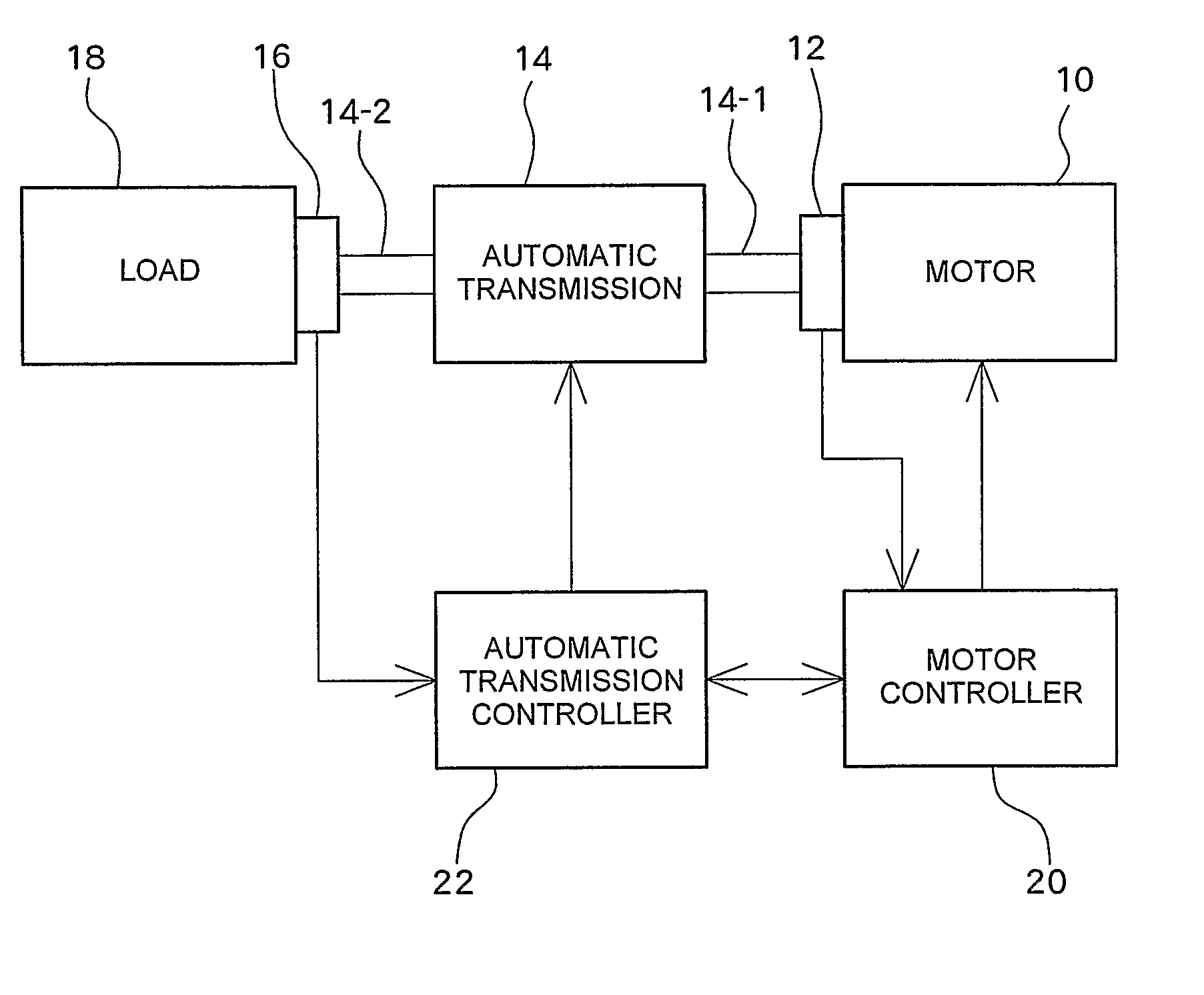
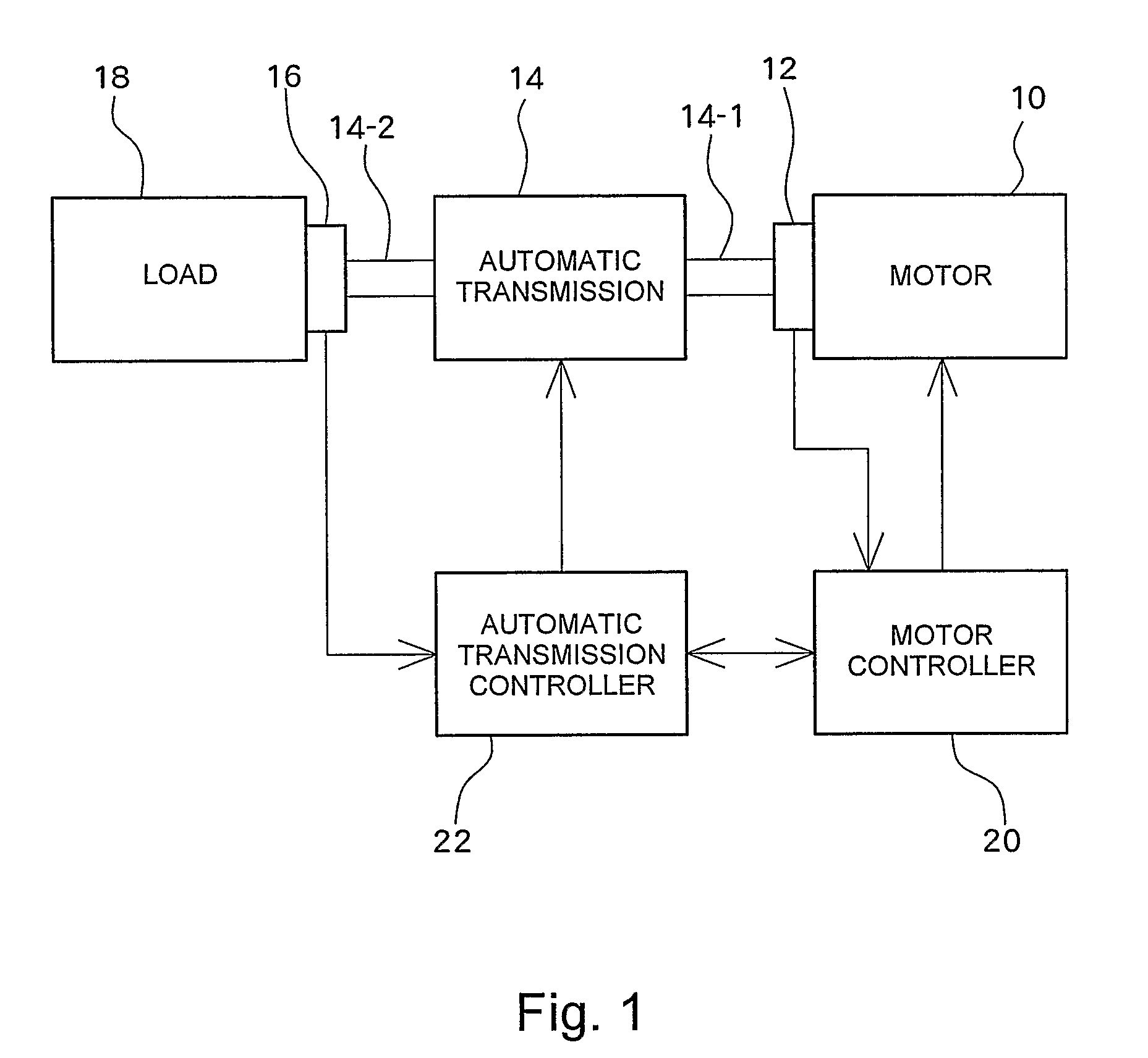
[0028]FIG. 1 shows a schematic configuration of an automatic transmission controlling system having a rotation speed detecting apparatus according to an embodiment of the present invention. The automatic transmission controlling system according the present embodiment comprises a motor 10, a resolver 12, an automatic transmission 14, an electromagnetic pickup sensor 16, a motor controller 20, and an automatic transmission controller 22, which will be described in detail below.

[0029]A rotor of the motor 10 is connected to an input shaft 14-1 of the automatic transmission 14. The automatic transmission 14 performs a speed change of drive power transferred from the motor 10 to the input shaft 14-1 and transfers the speed changed drive power to an output shaft 14-2. The drive power transferred to the output shaft 14-2 of the automatic transmission 14 is further transferred to a load ...


PUM


Abstract

An input shaft rotating speed detector detects an input shaft rotating speed Nin of an automatic transmission based on output signals from a resolver within a predetermined time period δt1. An output shaft rotating speed detector calculates the number of pulse signals output from an electromagnetic pickup sensor within the predetermined time period δt1, to detect an output shaft rotating speed Nout of the automatic transmission based on the time length of pulse intervals in the calculated number of pulse signals. With this configuration, the number of pulse signals used for calculating the output shaft rotating speed Nout can be changed, to thereby make a detection period of the output signals from the resolver used for calculating the input shaft rotating speed Nin be consistent with that of the pulse signals used for calculating the output shaft rotating speed Nout.

Description

[0001]This is a 371 national phase application of PCT / JP2006 / 311136 filed 26 May 2006, which claims priority of Japanese Patent Application No. 2005-164830 filed 3 Jun. 2005, the contents of which are incorporated herein by reference.TECHNICAL FIELD[0002]The present invention relates to a rotation speed detecting apparatus for detecting rotation speeds of a first rotating member and a second rotating member, and also relates to an automatic transmission controller having the rotation speed detecting apparatus.BACKGROUND ART[0003]As a sensor for detecting a rotation speed and a rotation angle of a rotating member, various types of detecting apparatuses have been used. Japanese Patent Laid-Open Publication No. Hei 7-306218, for example, discloses that a rotation speed of a wheel is detected using a wheel speed sensor of an electromagnetic pickup type. On the other hand, Japanese Patent Laid-Open Publication No. 2004-77136 discloses detection of a rotation angle of a motor using a reso...

Claims


Application Information

Patent Timeline
Patent Type & Authority Patents(United States)
IPC IPC(8): G01B7/30G01P3/42
CPCF16H59/36G01P3/56G01P3/48G01P3/44
Inventor ENDO, HIROATSUKAKUSE, KENTARO
Owner TOYOTA JIDOSHA KK
Why Eureka
Try Eureka