Display device

a display panel and display technology, applied in non-linear optics, instruments, optics, etc., can solve the problems of poor workability and poor workability, and achieve the effects of preventing the breakage preventing the positional shift of the display panel, and preventing the modulus of elasticity of the spacer

Active Publication Date: 2009-12-01
PANASONIC INTELLECTUAL PROPERTY CORP OF AMERICA +1
View PDF8 Cites 26 Cited by
  • Summary
  • Abstract
  • Description
  • Claims
  • Application Information

AI Technical Summary

Benefits of technology

[0015]An object of the invention is to provide a technology capable of facilitating attachment of the spacer to the support member, for example, in an assembling process of a liquid crystal display device.
[0033]Such a display panel is usually set up and used with the display panel in an upright position, that is, with cut end surfaces of the display panel oriented in horizontal and vertical directions. In this case, the spacer attached to a surface that faces the lower end surface of the display panel receives a force corresponding to the weight of the display panel. Thus, the spacer disposed at the lower side of the display panel is preferably made of a material more resistant to deformation than those for the other spacers. As described with reference to the device of (6), the modulus of elasticity of the spacer can be changed depending on its orientation at the time of installation so as to prevent a positional shift of the display panel due to the deformation of the spacer.

Problems solved by technology

This undesirably results in poor workability.
In particular, when the buffer spacer 3 is affixed to the first surface 1a of the support member 1, the buffer spacer 3 is easily misaligned, resulting in poor workability.

Method used


Image

  • Display device
  • Display device
  • Display device

Examples


Embodiment Construction

[0059]The invention will be described below in detail along with embodiments (examples) thereof with reference to the drawings. Throughout the drawings for explaining the examples, those having same functions have same reference characters and redundant description thereof will be omitted.

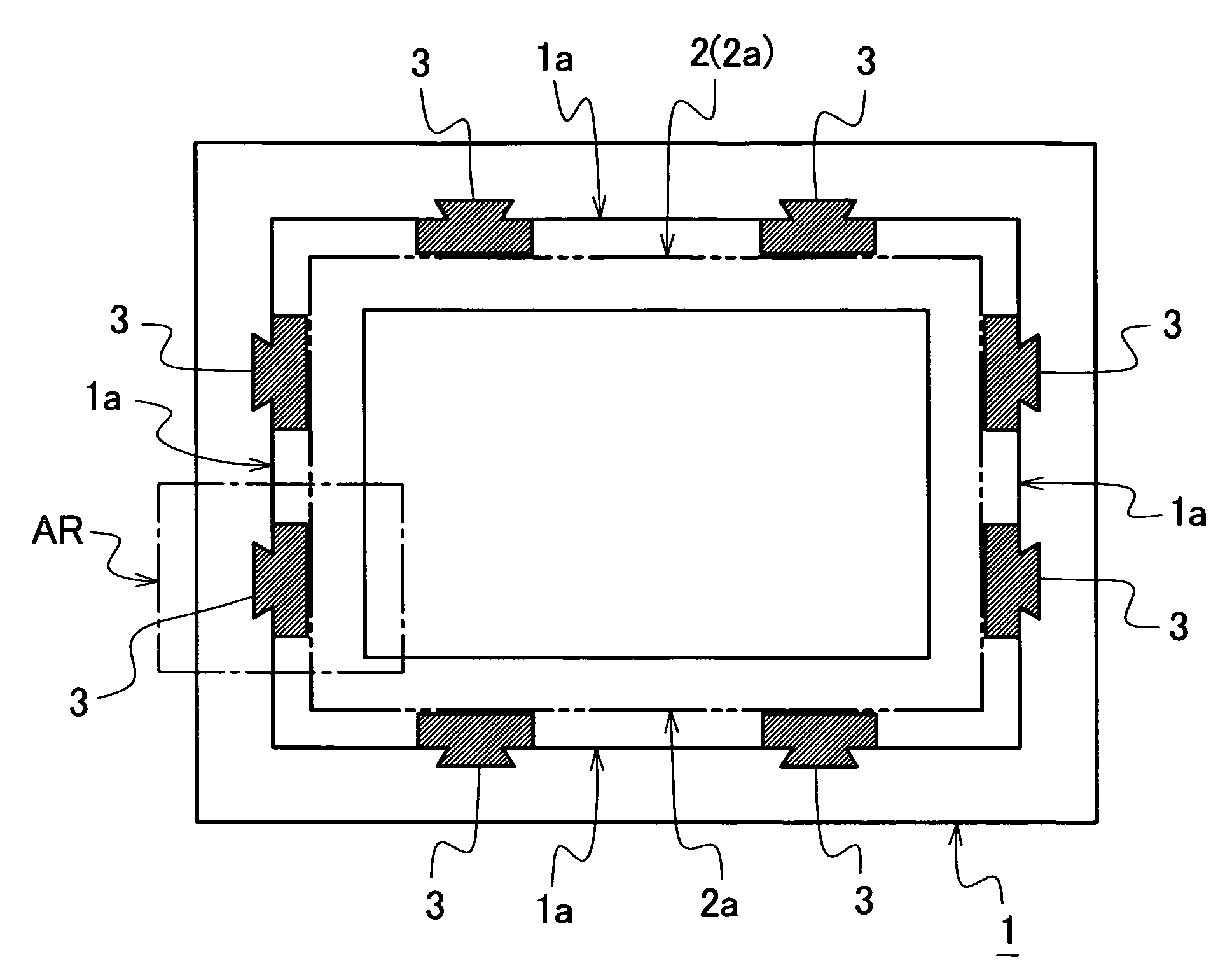
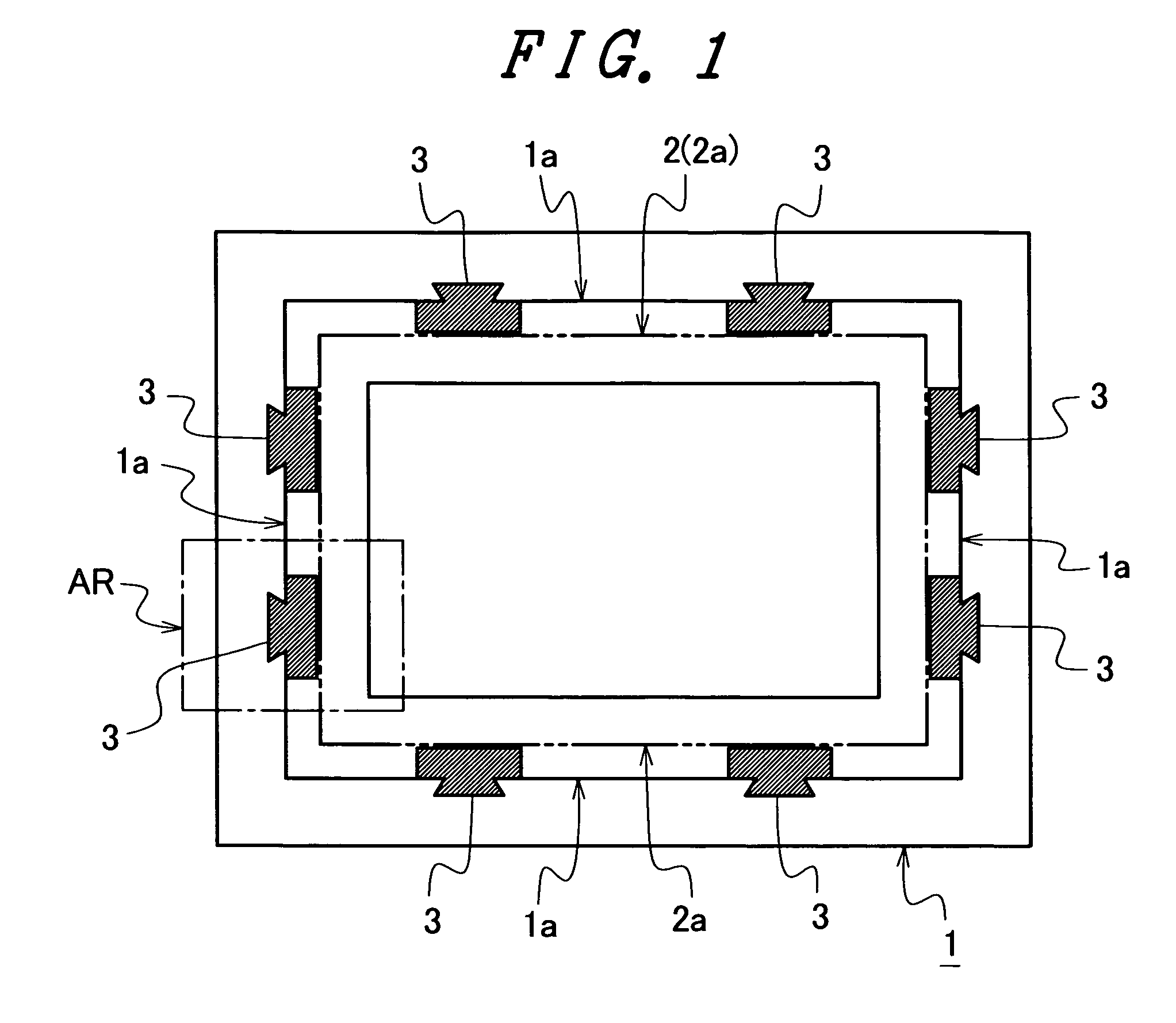
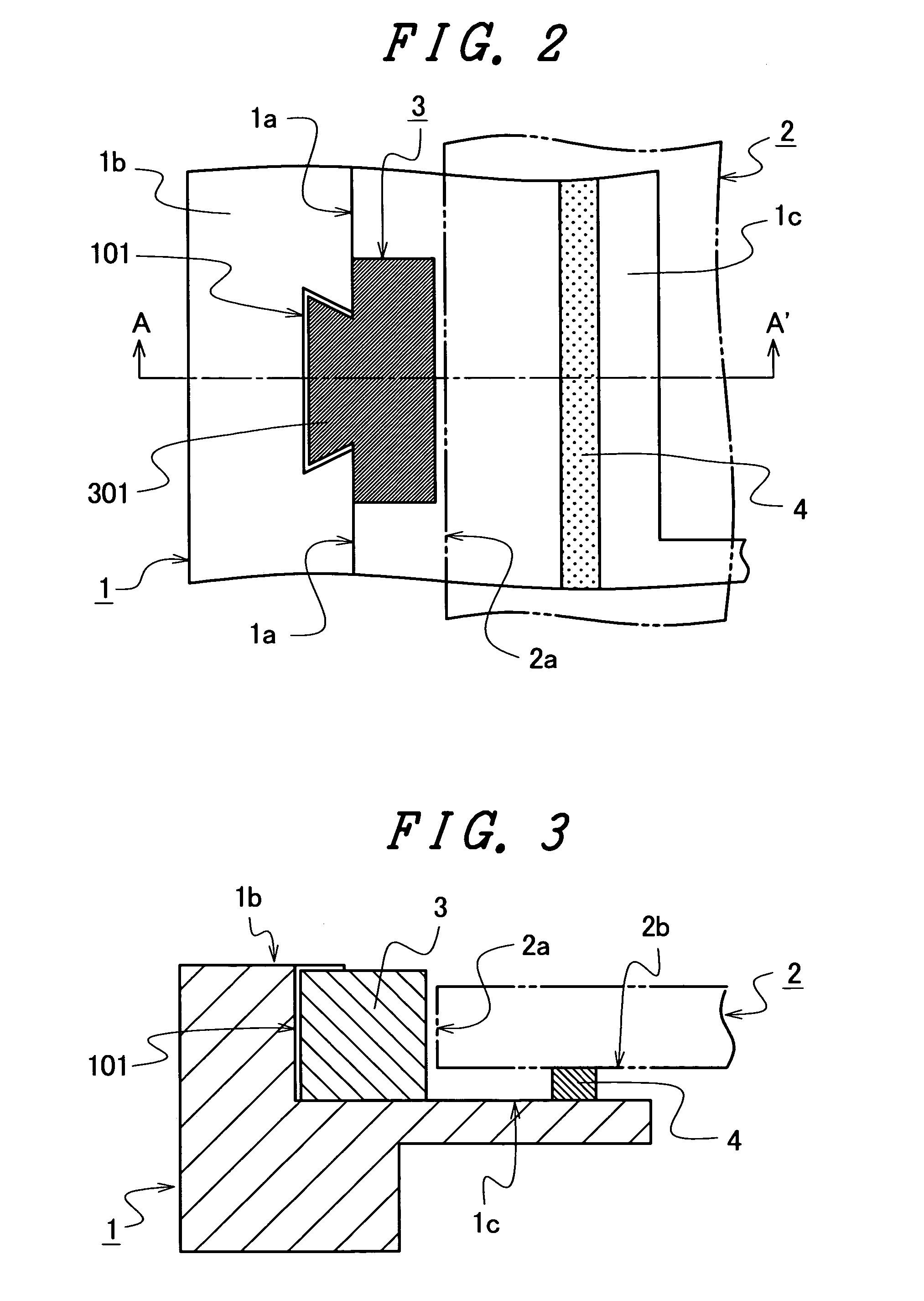
[0060]FIGS. 1 to 4 are diagrammatic views for explaining the main portion of the display device of the invention. FIG. 1 is a front view showing a schematic configuration of a support member and a spacer. FIG. 2 is an enlarged partial view of the area AR shown in FIG. 1. FIG. 3 is a cross-sectional view taken along the line A-A′ shown in FIG. 2. FIG. 4 is an exploded schematic view for explaining how to attach the spacer.

[0061]The display device of the invention is, for example, a display device like a liquid crystal display device, and includes a display panel, a support member that supports the display panel and a spacer that is interposed between the display panel and the support member.

[0062]In...


PUM

PropertyMeasurementUnit
central angleaaaaaaaaaa
modulus of elasticityaaaaaaaaaa
areaaaaaaaaaaa

Abstract

An object of the invention is to facilitate attachment of a spacer to a support member in an assembling process of a liquid crystal display device. A display device includes: a display panel, a support member that supports the display panel and a spacer that is interposed between a cut end surface of the display panel and a first surface of the support member, the first surface facing the cut end surface of the display panel. The support member has a recess that opens through the first surface and a second surface, which is connected to the first surface and extends away from the display panel. The spacer includes a spacer position securing portion inserted in the space of the recess of the support member and a buffer portion that is integral with the spacer position securing portion and protrudes from the open end at the first surface of the support member toward the cut end surface of the display panel.

Description

[0001]The present application claims priority from Japanese application JP2005-335421 filed on Nov. 21, 2005, the content of which is hereby incorporated by reference into this application.BACKGROUND OF THE INVENTION[0002]1. Field of the Invention[0003]The present invention relates to a display device, and particularly to a technology that is effectively applied to a display device, such as a liquid crystal display device, in which a display panel is supported by a support member.[0004]2. Description of the Related Arts[0005]Conventionally, a display panel of a liquid crystal display device is usually supported by a support member and a frame member.[0006]The support member is, for example, made of shaped resin and supports the display panel at the backside thereof. The frame member integrally holds the display panel, circuit components connected to the display panel, optical components and the like, and supports the display panel at the front side (forward side) thereof.[0007]The s...

Claims


Application Information

Patent Timeline
Patent Type & Authority Patents(United States)
IPC IPC(8): G02F1/1333
CPCG02F1/1333G02F1/133308G02F2201/503G02F2001/133354G02F2001/133322G02F1/133322G02F1/133354
Inventor TSUBOKURA, MASAKIAZUMA, YUJIFUMIKURA, TATSUYUKI
Owner PANASONIC INTELLECTUAL PROPERTY CORP OF AMERICA
Why Eureka
Try Eureka