Method and apparatus for telephone routing between PTN and PSTN

a telephone routing and telephone technology, applied in the field of telephone networks, can solve the problems of saving time and effort, and the general limitation of the use of a current network phone, and the inability of users within the phone network to be directly reached by one-stage dialing

Active Publication Date: 2009-12-01
IND TECH RES INST +1
View PDF6 Cites 13 Cited by
  • Summary
  • Abstract
  • Description
  • Claims
  • Application Information

AI Technical Summary

Benefits of technology

[0016]When the PSTN user B receives the call from the external line number and uses it to call back the PTN user A, the interface apparatus receives the PSTN number of user B via the external line the PSTN user B calls back with. With the data pair (the PSTN called party number, the external line number) as the key value to search the call-back table, the previously inserted call-back tag with matched PSTN called party number and the external line number can be found. With the PTN user identifier stored in the matched call-back tag, the present invention can route the incoming call to the internal telephony device having the PTN user identifier and accomplish the one-stage dialing.

Problems solved by technology

This saves time and effort for phone number look up and phone number key in.
In spite of the recent out booming of network phone development, there is one general limitation, however, to the use of a current network phone.
Unless with the direct inward dialing (DID) service provided by an intelligent phone network, a user within a phone network cannot be directly reachable by one-stage-dialing.
Such limitation also exists in the phone communication between users in a conventional private phone system and the users from a PSTN.
The two-stage dialing limitation for a PTN system is either due to the private number plan used in a PTN other than the public numbering used in the PSTN, or due to the number of external leased lines which connect a PTN to a PSTN is less than the number of users in the PTN for economic reasons.
When user B uses this caller ID to call back PTN user A, the frustration of two-stage dialing still exists.

Method used


Image

  • Method and apparatus for telephone routing between PTN and PSTN
  • Method and apparatus for telephone routing between PTN and PSTN
  • Method and apparatus for telephone routing between PTN and PSTN

Examples


Embodiment Construction

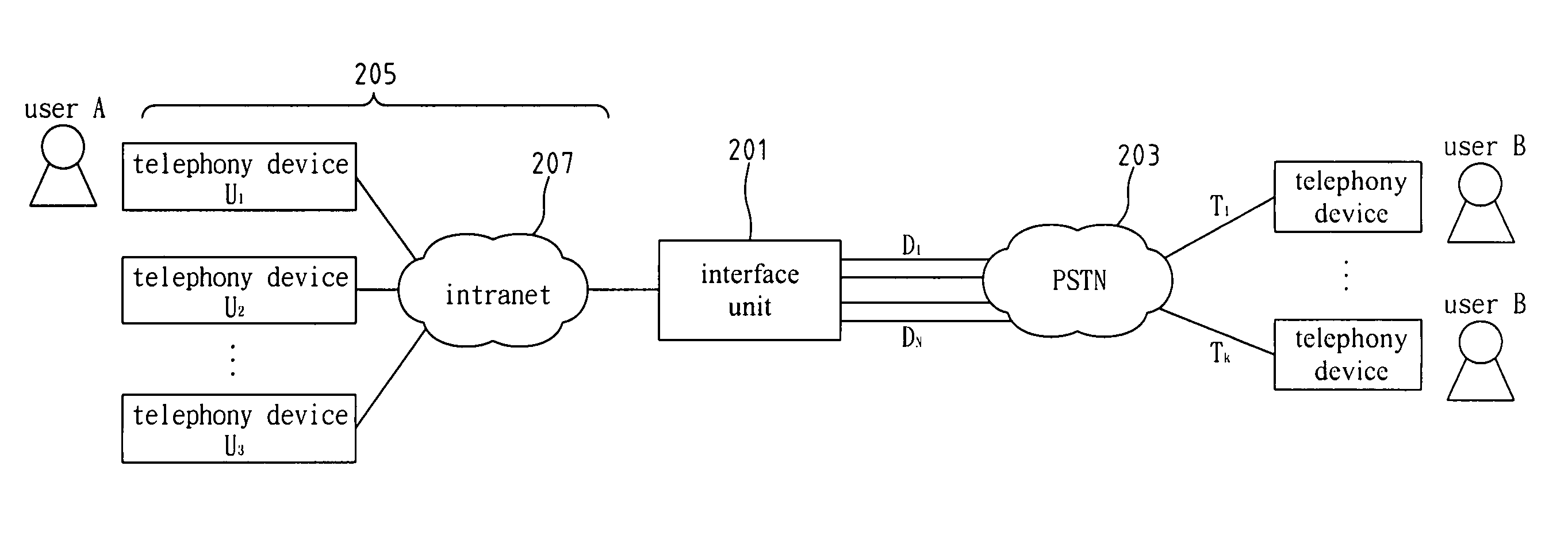
[0026]FIG. 2 a diagram illustrating a network phone environment that the present invention can be applied to. Referring to FIG. 2, a telephone routing apparatus according to the present invention comprises an interface unit 201 which provides a connection between a PSTN 203 and a PTN 205. The interface unit 201 connects to the PSTN 203 via N number of external lines. Such N external lines are assigned with the phone numbers D1-DN, respectively. This interface unit 201, on the other hand, connects to M number of internal telephonic apparatuses via an intranet 207. The PTN 205 includes the intranet 207 and the M number of internal telephony devices. Each of the internal telephony devices has its own identifier. Such M identifiers are noted as U1-UM, respectively. There are K numbers of PSTN receivers, which are assigned with phone numbers T1-TK, respectively.

[0027]Please be noted that, such interface unit 201 can be included in an interface apparatus, such as a branch switch, a key sy...


PUM


Abstract

Disclosed is a method and apparatus applicable to an interface between PSTN and PTN for telephone routing. The interface includes a branch switch, a key system, a network branch switch, and media gateway, etc. The telephone routing method and apparatus of the present invention creates, maintains, and utilizes a call-back routing table to enable a specified PSTN user to call the callback external leased line to reach a specified PTN user in a one-stage dialing manner. The process of one-stage dialing includes PTN call origination to PSTN, PSTN call origination to PTN, and callback tag insertion in the call-back routing table. The call-back routing table consists of a plurality of call-back tags. Each call-back tag consists of at least a data triple, i.e. PTN user identifier, PSTN called party telephone number, and callback leased line identifier.

Description

FIELD OF THE INVENTION[0001]The present invention generally relates to telephone networks, and more specifically to a method and apparatus for telephone routing between a private telephone network (PTN) and a public switched telephone network (PSTN).BACKGROUND OF THE INVENTION[0002]Caller ID has been a popular service provided by public wired and mobile phone networks. Wired phones or mobile phones with caller ID feature are also popularly available at stores almost everywhere. The caller ID feature not only allows users to screen incoming calls, but also grants users the advantage of direct callback capability with the caller ID stored. This saves time and effort for phone number look up and phone number key in.[0003]In spite of the recent out booming of network phone development, there is one general limitation, however, to the use of a current network phone. A PSTN user cannot take the advantage of the caller ID feature to call back a user from a network phone. Unless with the di...

Claims


Application Information

Patent Timeline
Patent Type & Authority Patents(United States)
IPC IPC(8): H04M3/00
CPCH04M3/42195H04Q3/0045H04M7/009
Inventor CHANG, MING-FENGLIN, YI-BINGLIANG, CHING-FENG
Owner IND TECH RES INST
Why Eureka
Try Eureka