Drive device for wire-type window regulator

a technology of window regulator and drive device, which is applied in the direction of door/window fittings, wing accessories, transportation and packaging, etc., can solve the problems of work efficiency drop, and achieve the effect of convenient work and convenient work

Inactive Publication Date: 2009-12-08
MITSUI KINZOKU ACT
View PDF24 Cites 6 Cited by
  • Summary
  • Abstract
  • Description
  • Claims
  • Application Information

AI Technical Summary

Benefits of technology

[0010]The present invention has been completed with such issues of the related art in mind and has an object to provide a drive device for a wire-type window regulator that makes it possible to easily carry out a series of work for assembling from a phase in which a wire is wound on a drum to a phase in which the drum is coupled to a motor.
[0011]To achieve the above object, a wire-type window regulator, of the present invention, comprises a motor serving as a drive source, a drum having an outer periphery formed with a recess in which a wire is wound, a cover having a top surface and an inner wall, formed in a cylindrical shape in cross section, by which a drum accommodating space is defined, wherein under a condition where the drum is accommodated in the drum accommodating space, the wire is wound between the inner wall and the recess of the drum to prevent dropout of the wire, a drive bore portion, formed in a bottom surface of the drum at a rotational axis thereof, which has a shape to correspond to a cross-sectional shape of an output shaft of the motor, a rotation operator formed at a rotation center of a top surface of the drum, and an operation bore portion formed in the top surface of the cover such that under a condition where the drum is accommodated in the cover, the rotation operator is exposed to an inside of the operation bore portion.
[0012]With such a structure, the drum accommodated in the cover can be rotated for winding up the wire on the drum by manually rotating and operating, or using an electromotive tool, the rotation operator of the drum, exposed to the operation bore portion, through the operation bore portion formed in the top surface of the cover while keeping the drum within the cover. Accordingly, it becomes easy to perform work for winding the wire. Also, leaving the rotation operator under engaged condition after completing the winding-up operation avoids the antirotation of the drum in a rewinding direction within the cover, making it easy for performing work for allowing the output shaft of the motor to be brought into engagement with the drive bore portion of the drum.

Problems solved by technology

However, with such related art technology, due to the presence of a need to block the rotation of the drum during a period in which after the wire is wound on the drum, the drum is accommodated within the cover upon which the output shaft of the motor is brought into engagement with the drive bore portion of the drum, issues have arisen with troublesome work, resulting in a drop in work efficiency.

Method used


Image

  • Drive device for wire-type window regulator
  • Drive device for wire-type window regulator
  • Drive device for wire-type window regulator

Examples


Embodiment Construction

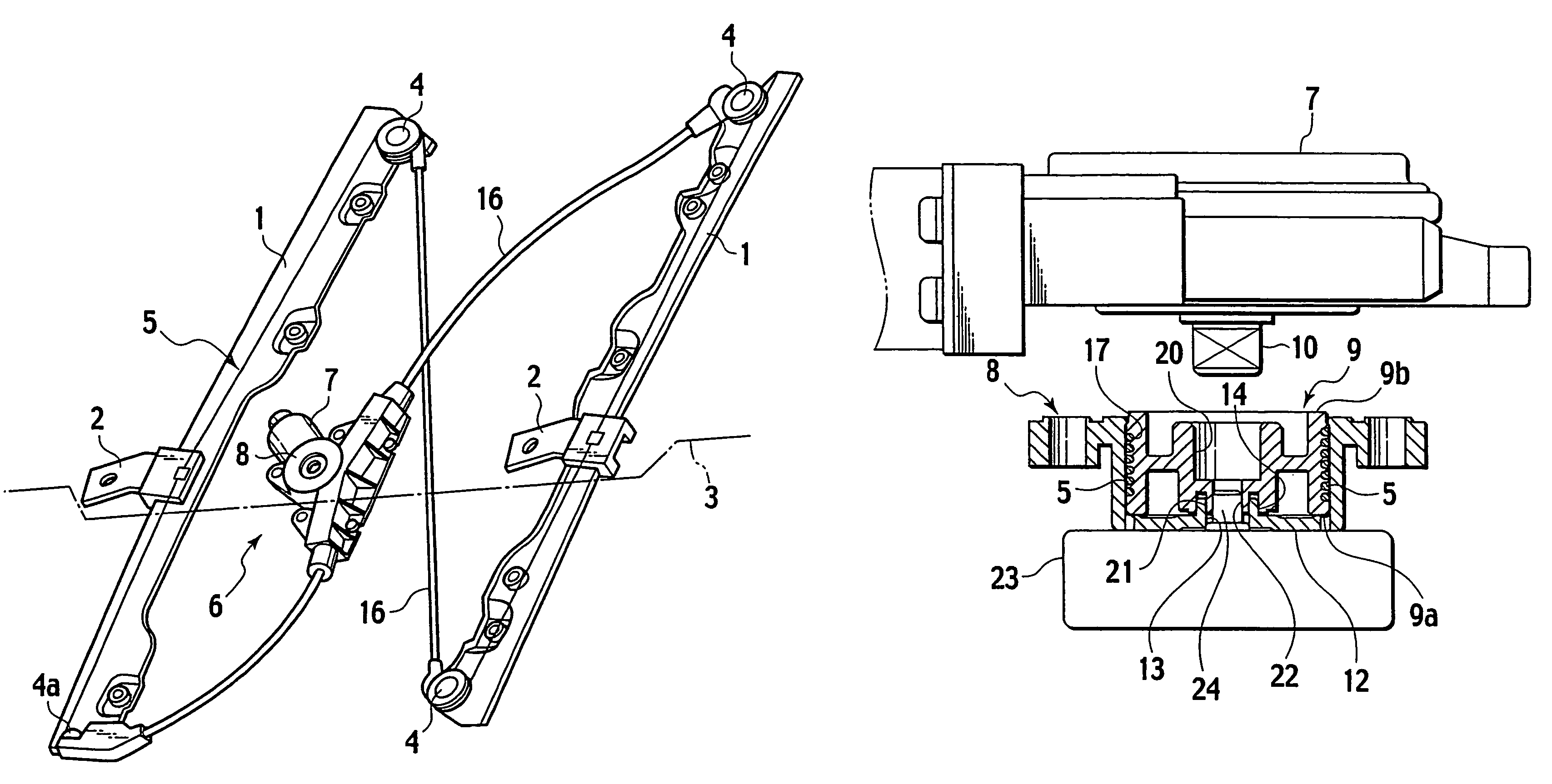
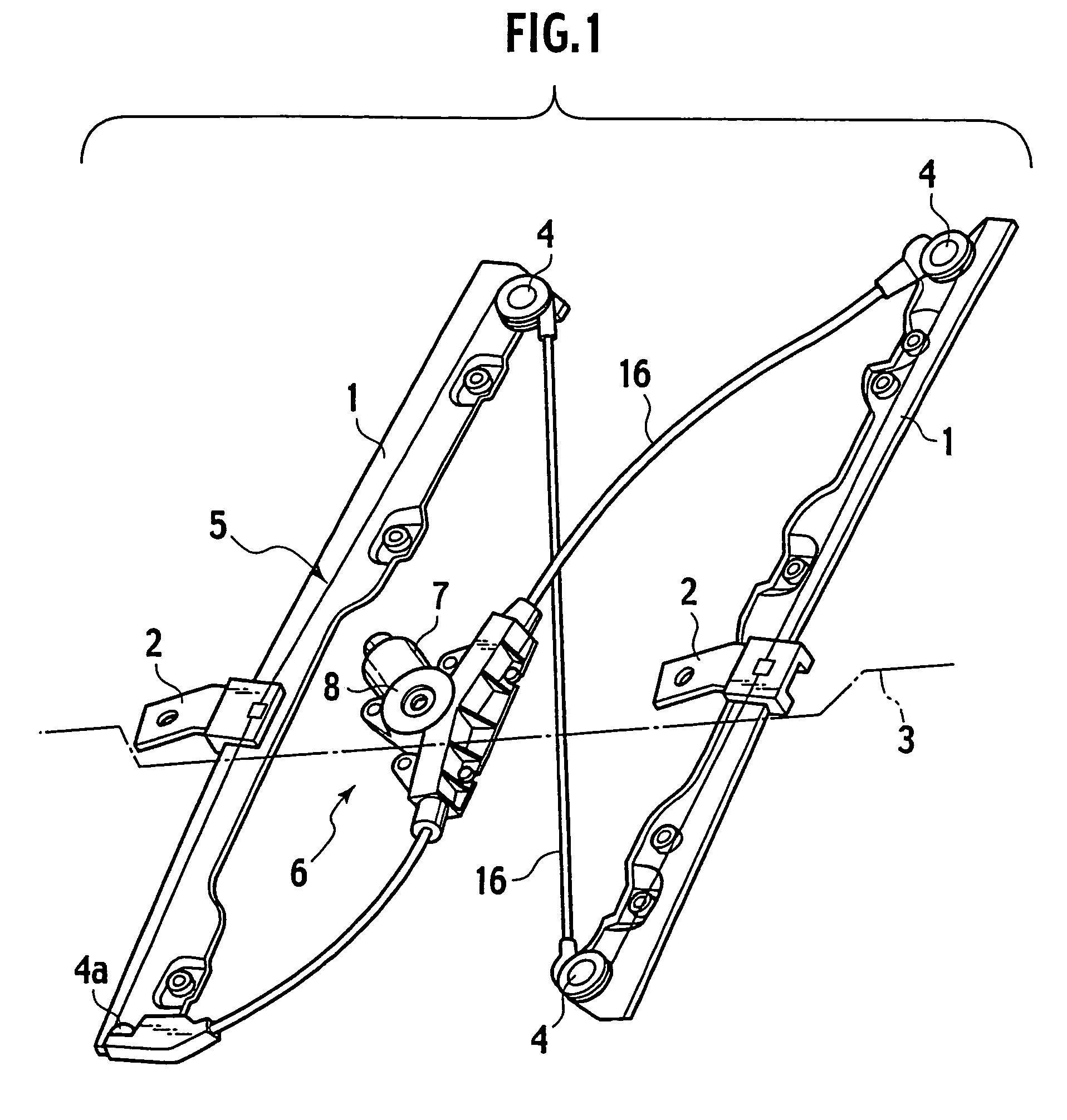
[0021]Now, one embodiment of the present invention is described with reference to FIGS. 1 to 8. As shown in FIG. 1, fixedly secured to a pair of fore and aft guide rails 1 fixedly mounted on a door (not shown) are vertically movable carrier plates 2 to which a window panel 3 is fixedly secured.

[0022]Disposed on the guide rails 1 at upper and lower areas thereof are pulleys 4 and wire guides 4a, on which a loop-shaped wire 5 is stringed. The carrier plates 2 engage with the wire 5 extending along each guide rail 1 to be vertically movable with the wire 5.

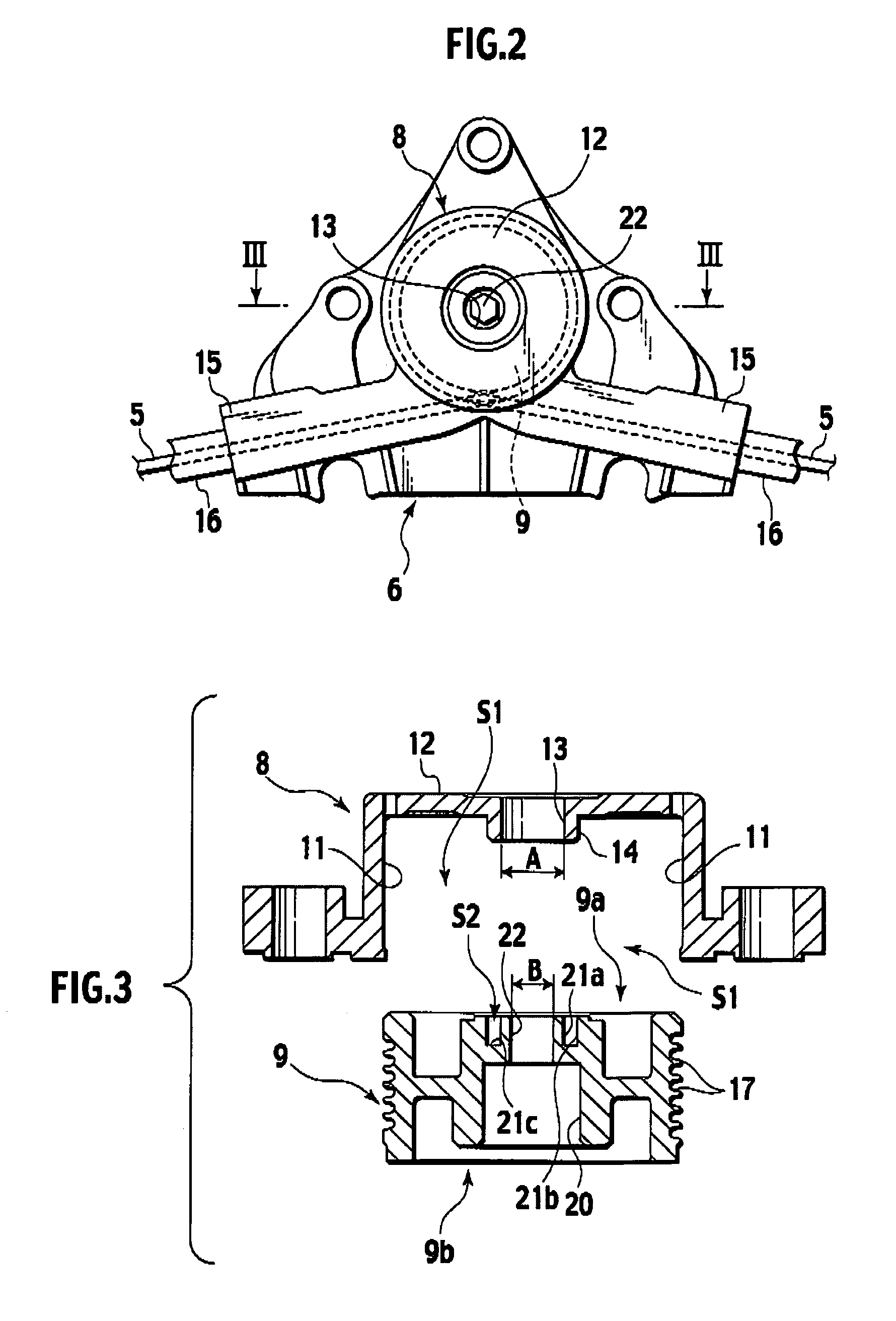
[0023]The wire 5 is arranged to extend in string segments crossing each other in an area between the pair of guide rails 1 and one of the string segments carries a drive device 6. The drive device 6 is comprised of a motor 7, a cover 8 and a drum 9.

[0024]The motor 7 is fixedly mounted to the guide rail 1 via a bracket (a fixing unit) that is not shown. The motor 7 is able to rotate an output shaft 10, formed in a quadrangle shape in ...


PUM


Abstract

A drive device for a wire-type window regulator is disclosed wherein a drum is accommodated in a cover and, under such a status, rotating and operating a rotation operator, exposed to an operation bore portion, enables work to be done for winding a wire. With the rotation operator kept in engagement with operation bore portion, the drum is avoided from rotating in a rewinding direction, making it easy to perform work for an output shaft of a motor to be brought into engagement with a drive bore portion of the drum.

Description

CROSS REFERENCE TO RELATED APPLICATIONS[0001]This invention is based upon and claims the benefit of priority from Japanese Patent Application No. 2004-121887, filed on Apr. 16, 2004; the entire contents of which are incorporated herein by reference.BACKGROUND OF THE INVENTION[0002]1. Field of the Invention[0003]The present invention relates to drive devices for a wire-type window regulator.[0004]2. Description of the Related Art[0005]Heretofore, in drive devices of wire-type window regulators for lifting and lowering window panels mounted to, for instance, vehicle doors has guide rails, fixedly mounted to the door, to be provided with a vertically movable carrier plate to which a window panel is fixedly secured. The carrier plate has been engaged with a wire stringed on the guide rails.[0006]The wire has a portion wound on an outer circumferential periphery formed in a spiral form on a sidewall of a drum. The drum is accommodated in an inside of a cover formed with an inlet and outl...

Claims


Application Information

Patent Timeline
Patent Type & Authority Patents(United States)
IPC IPC(8): E05F11/48B60J1/17E05F15/10E05F15/16
CPCE05F15/689E05Y2900/55
Inventor OOTSUKI, YASUOTATSUMI, HISATO
Owner MITSUI KINZOKU ACT
Why Eureka
Try Eureka