
Fuel supply device

a fuel supply device and fuel technology, applied in the direction of liquid fuel feeders, machines/engines, charge feed systems, etc., can solve the problems of increasing the cost of the fuel supply device, and achieve the effect of quick degrad

Inactive Publication Date: 2009-12-08
DENSO CORP
View PDF22 Cites 32 Cited by
  • Summary
  • Abstract
  • Description
  • Claims
  • Application Information

AI Technical Summary

Benefits of technology

The present invention provides a fuel supply device for vehicles that reduces manufacturing costs and simplifies the structure of the device. The device includes a subtank, a fuel pump, and a filter member. The filter member is connected to a first suction port of the fuel pump for filtering the fuel supplied to the external unit, and is also connected to a second suction port of the fuel pump for filtering the fuel pumped into the subtank. The filter member includes a case with a partition wall that defines a first and a second flow passage, with the first filter element located in the first flow passage and the second filter element located in the second flow passage. The device is designed to reduce the length of the flow passages for pumping up fuel from the sub tank and from the external unit, which helps to decrease manufacturing costs. Additionally, the device is designed to reduce the length of the filter member, which simplifies the assembly process and reduces the likelihood of foreign matter accumulation.

Problems solved by technology

In this construction, the two filter members are required for manufacturing a single fuel supply device, and use of the two filter members increases the man hour for assembling the fuel supply device, leading to an increase of costs of the fuel supply device.

Method used


Image

  • Fuel supply device
  • Fuel supply device
  • Fuel supply device

Examples


first embodiment

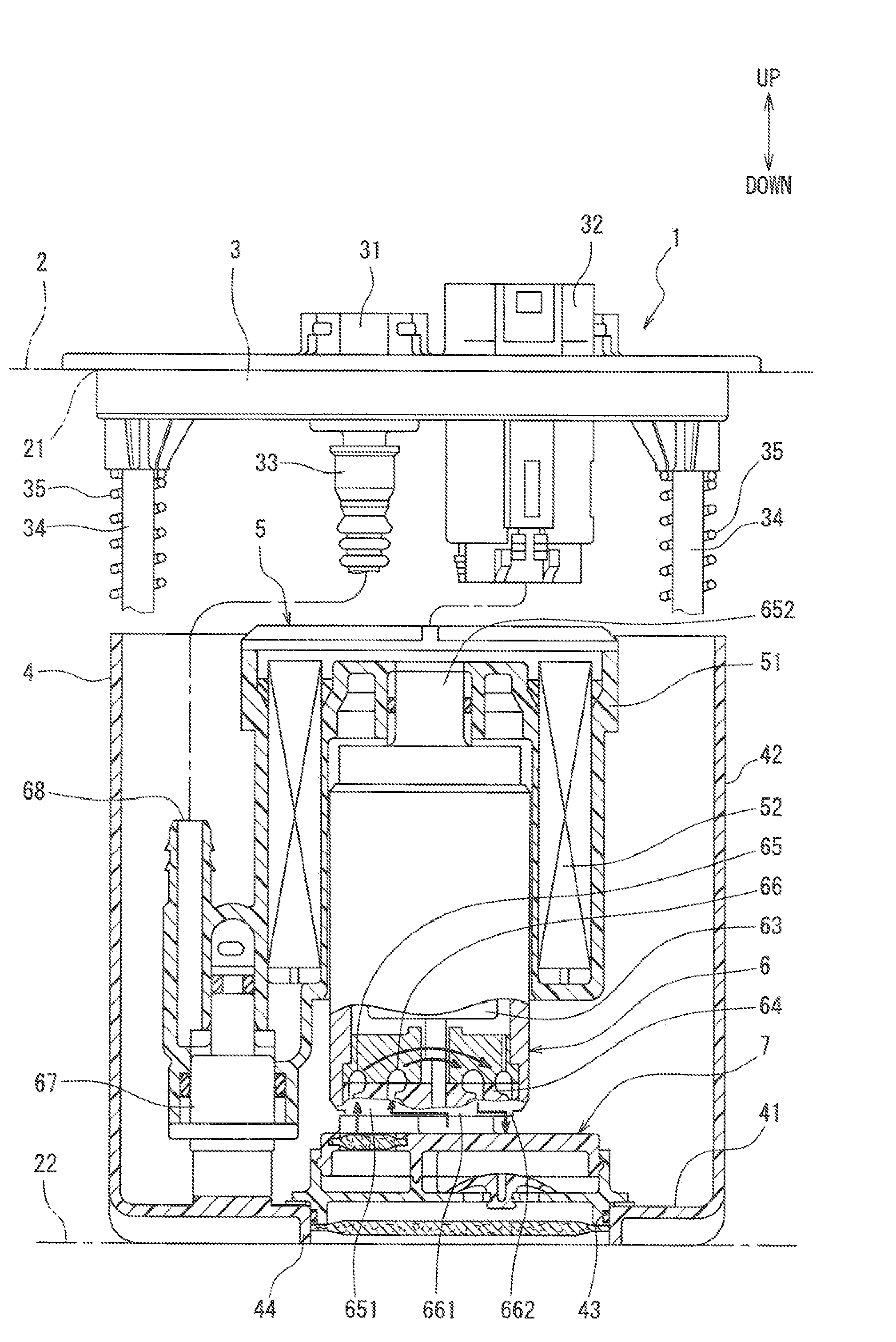
[0073]FIG. 1 is a sectional view showing a state where a fuel supply device 1 is arranged in a fuel tank 2. The upward-downward direction shown in an arrow in FIG. 1 shows the gravity direction in a state where the fuel tank 2 is mounted in a vehicle. The fuel supply device 1 is a device for supplying fuel in the fuel tank 2 to a fuel consumption device (for example, internal combustion engine). As shown in FIG. 1, the fuel supply device 1 is inserted from an opening 21 of the fuel tank 2 into the fuel tank 2 to be arranged therein and is located on the bottom surface 22 of the fuel tank 2. A flange 3 is attached on the opening 21 to close the opening 21 therewith.

[0074]The fuel supply device 1 is constructed by attaching a pump unit 5 and the like to a sub tank 4 accommodated in the fuel tank 2. The sub tank 4 is jointed to the flange 3 with shafts 34.

[0075]The flange 3 is made of a resin and is formed substantially in a disc-shape. The flange 3 is resin-molded integrally with a fu...

second embodiment

[0121]A second embodiment of the present invention will be explained with reference to FIGS. 5 and 6.

[0122]As shown in FIGS. 5 and 6, a pumping-up fuel filter 99a is configured as a result of providing a filter body 992, which is made of non-woven cloth similar to the first embodiment, for a substantially annular ring member 991. The pumping-up fuel filter 99a of the present embodiment is fixed by press-fitting the ring member 991 into an inner wall of the cylindrical portion 91 in the lower casing 9. In consequence, the pumping-up fuel filter 99a can be easily mounted to the filter assembly 7.

third embodiment

[0123]A third embodiment of the present invention will be explained with reference to FIGS. 7 and 8.

[0124]As shown in FIGS. 7 and 8, a pumping-up fuel filter 99b includes a substantially annular ring member 993, a disc member 994 arranged substantially in the center of the ring member 993, and hub members 995 connecting the ring member 993 to the disc member 994. Filter bodies 996 made of non-woven cloth as in the case of the first embodiment are provided in spaces between the ring member 993 and the disc member 994. The pumping-up fuel filter 99b of the present embodiment is fixed by press-fitting the ring member 993 into the inner wall of the cylindrical portion 91 in the lower casing 9. In consequence, the pumping-up fuel filter 99b can be easily mounted to the filter assembly 7.

[0125]The pumping-up fuel filter 99b of the present embodiment is configured to support the filter body 996 by the disc member 994 provided in the substantially central portion and the hub member 995. The...


PUM


Abstract

A fuel supply device includes a subtank in a fuel tank, a fuel pump in the subtank having a first pump unit suctioning fuel in the subtank to supply fuel to an external equipment and a second pump unit suctioning fuel outside the subtank to pump fuel into the subtank, and a filter connected to a first suction port of the first unit and a second suction port of the second unit and filtering supply fuel supplied to the equipment and pump fuel pumped into the subtank. The filter includes a case, a first filter, and a second filter. The first filter in a first passage of the case directing fuel in the subtank into the first port filters the supply fuel. The second filter in a second passage of the case directing fuel outside the subtank into the second port filters the pump fuel.

Description

CROSS-REFERENCE TO RELATED APPLICATION[0001]This application is based on and incorporates herein by reference Japanese Patent Application No. 2007-191141 filed on Jul. 23, 2007 and Japanese Patent Application No. 2008-112992 filed on Apr. 23, 2008.BACKGROUND OF THE INVENTION[0002]1. Field of the Invention[0003]The present invention relates to a fuel supply device.[0004]2. Description of Related Art[0005]There is known a fuel supply device for stably supplying fuel even if a remaining amount of the fuel in a fuel tank decreases (for example, refer to U.S. Pat. No. 5,596,970). The fuel supply device in U.S. Pat. No. 5,596,970 is accommodated in the fuel tank. The fuel supply device is provided with a sub tank for accumulating a part of the fuel in the fuel tank, and a fuel pump accommodated in the sub tank. The fuel pump includes a first pump unit for suctioning the fuel in the sub tank to supply the suctioned fuel to a fuel consumption device, and a second pump unit for suctioning fu...

Claims


Application Information

Patent Timeline
Patent Type & Authority Patents(United States)
IPC IPC(8): F02M37/00F02M37/04
CPCF02M37/106F02M37/025F02M2037/228F02M2037/226F02M2037/225F02M37/44F02M37/46F02M37/50
Inventor YAMADA, KATSUHISATANAKA, MASAAKIKAWAJIRI, CHIAKI
Owner DENSO CORP
Learn More