Led lamp structure

a technology of led lamps and circuit boards, which is applied in the direction of transportation and packaging, semiconductor devices for light sources, lighting and heating apparatus, etc., can solve the problems of reducing the cooling effect of the light source driving circuit boards, and achieve the effects of improving the cooling effect, increasing the luminous quantity, and saving energy

Inactive Publication Date: 2009-12-08
PRIMO LITE
View PDF6 Cites 134 Cited by
  • Summary
  • Abstract
  • Description
  • Claims
  • Application Information

AI Technical Summary

Benefits of technology

[0013]Further, given that the light source driving circuit board is arranged in the accommodation chamber which is located at the flared end of the housing with a larger space, minimization to the light source driving circuit board, as needed by the conventional art because of limited space, is unnecessary. As such, electronic components on the light source driving circuit board require only a normal dimension. In addition, a convenient assembly can be facilitated, and an improved cooling effect be obtained.
[0014]An improvement on ventilation prevents the light source driving circuit board from being damaged due to the heat produced from per se; nor the problem encountered by the conventional art occurs owing to an undesirable ventilation that the light source driving circuit board is confined in a narrow internal space of the support and that the electronic components on the light source driving circuit board may be softened or even melted. Therefore, the LED lamp structure according to the present invention can be more durable and reliable.
[0016]The housing includes a wall surrounding the accommodation chamber, where the wall is provided with at least one vent, thereby improving cooling effect on the housing and on the light source driving circuit board which is located inside the housing. The at least one vent may be elongated, circular, square or others, providing the air circulation passway for heat convection.
[0017]The LED light source may be determined by condition of use, namely, option may be directed to greater luminous quantity, more energy saving, or longer life of use.
[0018]The lens has a predetermined illuminating angle, so that the light beams projected from the LED light source can be limited to a specific angle, upon a design on the illuminating angle. For example, a focusing effect may be made to the LED light source so that brighter light beams can be obtained; or a diffusion effect may be made, through designing a predetermined illuminating angle, so that softer light beams can be obtained. In other words, through a design on the lens for a predetermined illuminating angle, a desirable illumination effect on the LED light source can be obtained.

Problems solved by technology

Further, given that the light source driving circuit board is arranged in the accommodation chamber which is located at the flared end of the housing with a larger space, minimization to the light source driving circuit board, as needed by the conventional art because of limited space, is unnecessary.

Method used


Image

  • Led lamp structure
  • Led lamp structure
  • Led lamp structure

Examples


Embodiment Construction

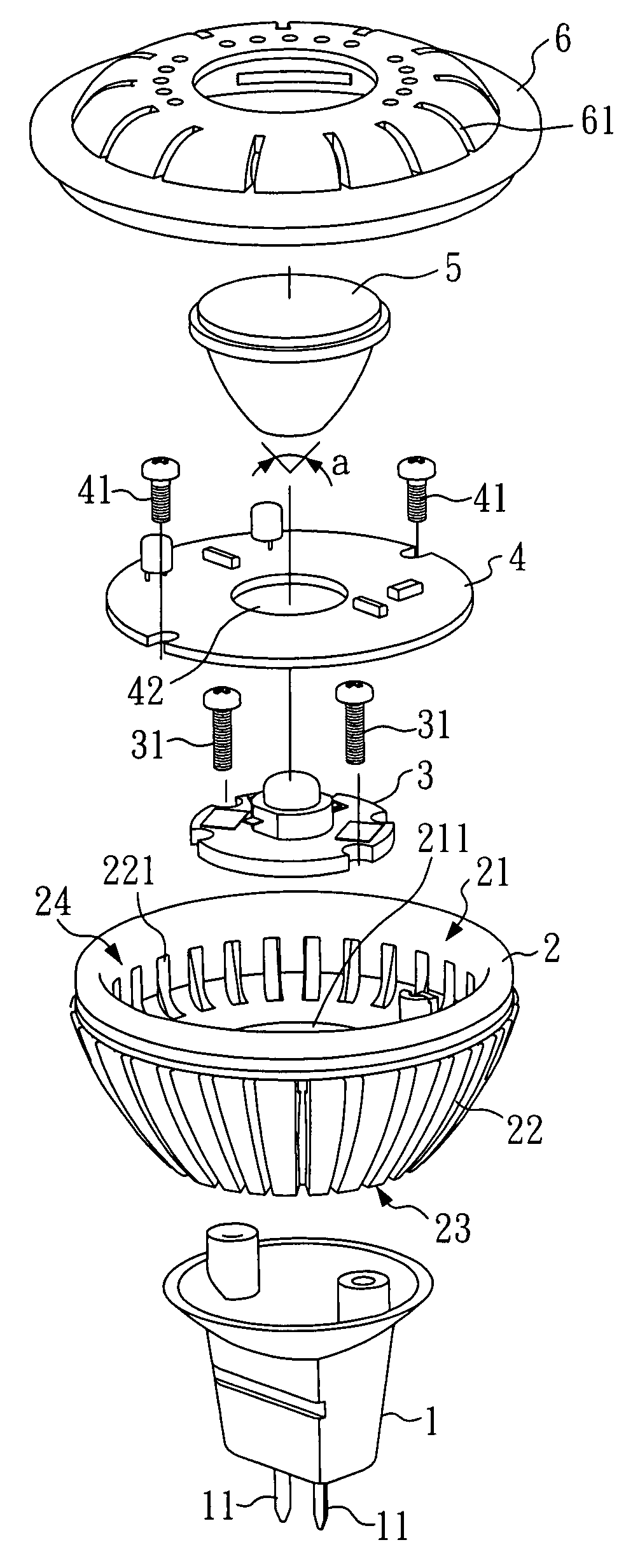
[0024]Referring to FIGS. 3 and 4, the LED lamp structure exemplified as a preferred embodiment of the present invention relates to Model No. MR16. The LED lamp structure comprises a housing 2, a support 1, an LED light source 3, a light source driving circuit board 4, a lens 5, and a cover 6. As shown, the housing 2 has a horn-like shape with a converged end 23 and a flared end 24, wherein the flared end 24 is formed with an accommodation chamber 21 and a recessed portion 211.

[0025]The housing 2 is made of metal, or preferably in the present invention, aluminum, where the housing 2 includes a wall 22 surrounding the accommodation chamber 21. Further, the wall 22 is provided with a plurality of vents 221 communicating the accommodation chamber 21 with outside of the housing 2, where the vents 221 are each elongated. Alternatively, the vents 221 may be circular, square or others.

[0026]The support 1 is arranged underneath the converged end 23 of the housing 2, where the support 1 is pr...


PUM


Abstract

An LED lamp structure includes a housing, a support, an LED light source, a light source driving circuit board, a lens, and a cover. The housing has a horn-like shape with a converged end and a flared end, wherein the flared end is formed with an accommodation chamber; the converged end is arranged with a support, and the accommodation chamber receives an LED light source, a light source driving circuit board, and a lens; and the cover is engaged with the flared end of the housing. Given that the light source driving circuit board is located at the flared end of the housing with a larger space. As such, an improved cooling effect can be obtained and that the electronic components can be more durable and reliable. And the lens has a predetermined illuminating angle, so that a desirable illumination effect on the LED light source can be obtained.

Description

BACKGROUND OF THE INVENTION[0001]1. Field of the Invention[0002]The present invention relates to a lamp structure in which LEDs are used as a light source, and more particularly, to an LED lamp structure adapted to direct driving and to increasing cooling effect.[0003]2. Description of Related Art[0004]Nowadays lamps available in the market, such as those modeled in GU10, E12, MR16 or E27 lampbase, are used to project light beams on articles so as to improve brightness, aesthetics, and displaying effect of the articles. Examples can be found in art galleries where art works and jewelries are illuminated with lamps. A light fitting is then formed with a lamp structure arranged into a frame.[0005]FIG. 1 illustrates a perspective view of a conventional lamp structure; and FIG. 2 illustrates a cross-sectional view of the conventional lamp structure. A lamp structure 9, known as Model MR 16, comprises a reflector 91, a housing 92, and a support 93, wherein the reflector 91, the housing 9...

Claims


Application Information

Patent Timeline
Patent Type & Authority Patents(United States)
IPC IPC(8): F21V3/00
CPCF21K9/137F21V19/0055F21V17/12F21V23/006F21Y2101/02F21V29/83Y10S362/80F21K9/233F21K9/238F21Y2115/10
Inventor CHIU, CHIA-FA
Owner PRIMO LITE
Why Eureka
Try Eureka