
System and method for transferring data

a technology of data and system, applied in the field of system and method for transferring data, can solve problems such as security problems

Active Publication Date: 2009-12-08
CALLAHAN CELLULAR L L C
View PDF15 Cites 28 Cited by
  • Summary
  • Abstract
  • Description
  • Claims
  • Application Information

AI Technical Summary

Benefits of technology

[0012]To initiate a transfer, the source SDT engine tells the destination SDT engine that data is available. Next the destination SDT engine then sends a data request to the source SDT engine. The source SDT engine then sends data to the destination SDT engine. In contrast to a push model, this pull model eliminates problems with incoming data that the destination SDT engine does not have space for by leaving control with the destination SDT engine.

Problems solved by technology

This presents not only a security problem if a node wants to keep its address space private, but also requires that at least one of the systems have intimate knowledge about the hardware of the other system.
Moreover, transferring data between nodes often requires close synchronization of hardware resources on both ends of the transfer during the data transfer—for instance, between the DMA engine, a hard drive controller and memory.

Method used


Image

  • System and method for transferring data
  • System and method for transferring data
  • System and method for transferring data

Examples


Embodiment Construction

1. Overview

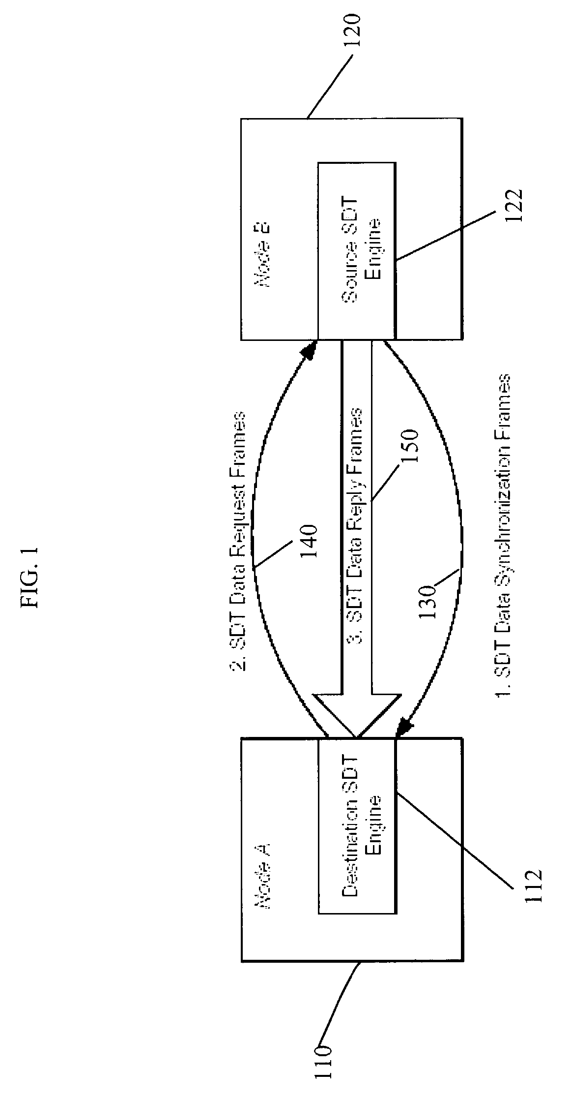
[0021]Referring now to FIG. 1, there is shown destination node 110 and source node 120. Associated with destination node 110 is destination SDT engine 112 and with source node 120 is source SDT engine 122.

[0022]a. Flow

[0023]Also shown in FIG. 1 is a high level overview of the flow data utilizing the present invention. The data transfer protocol of the present invention is as follows:[0024]Step 1: Source SDT engine 122 sends a SDT data synchronization frame 130 to destination SDT engine 112 notifying destination SDT engine 112 that there is data that source SDT engine 122 has to send it.[0025]Step 2: Destination SDT engine 112 sends a SDT data request frame 140 to source SDT engine 122 requesting the data.[0026]Step 3: In response to data request frame 140, source SDT engine 122 sends one or more data reply frames 150, which carries, among other things, the data, to destination SDT engine 112.

[0027]Although not shown, data synchronization frame 130, data request frame 140 ...


PUM


Abstract

A system and method for transferring data between two relatively autonomous processors using a sockets interface. In particular, a source SDT (“socket data transfer”) engine tells a destination SDT engine that data is available. Next the destination SDT engine then sends a data request to the source SDT engine. The source SDT engine then sends data to the destination SDT engine.

Description

CROSS-REFERENCE TO RELATED APPLICATIONS[0001]The patent application claims the benefit and priority from U.S. Provisional Patent Application No. 60 / 389,361 filed on Jun. 17, 2002, which is hereby incorporated by reference in its entirety.BACKGROUND OF THE INVENTION[0002]1. Field of the Invention[0003]This invention generally relates to a system and method for transferring data between two relatively autonomous processors, one on each side of the data transfer operation.[0004]2. Description of the Related Art[0005]When two nodes on a network need to exchange data over a network, current methods often require that the nodes expose their address spaces to each other. For instance, in a direct memory access (“DMA”) operation, the DMA engine needs to know the memory addresses of where to retrieve the data and where to place the data. This presents not only a security problem if a node wants to keep its address space private, but also requires that at least one of the systems have intimat...

Claims


Application Information

Patent Timeline
IPC IPC(8): G06F9/54G06F13/38G06F13/42G06F15/16
CPCG06F13/4252
Inventor MAYHEW, DAVIDBROCCO, LYNNE MICHELLE
Owner CALLAHAN CELLULAR L L C
Learn More